Hello,
I'm planning on doing a lm338 snubberized power supply. I want to use it for a ta2020 amp and another one for a tda7297 amp. I guess the supply voltage should be about 13.5V and 16V respectively.
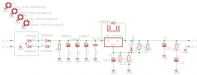
I made the schematic in Eagle but I got lost at pcb layout. I haven't done any pcb and I don't know what's best as far as parts layout, spacing, trace width etc. I plan on making it myself with one of the few methods available so I'm looking for a single sided pcb. Also I want to add the option of two parallel resistors for the resistors that set the voltage for lm338. I guess it's nice to have the option of dialing the voltage as close as possible. I'm planning on using the to-220 version. Also at this moment I'm oscillating between lm338 and lt1084. Current requirement is about 2-3A maximum so any should do. The LT1084 needs a 22uF tantalum or 150uF electrolytic on the output as that's part of the frequency compensation network. I guess a 5mm lead spacing on that capacitor would enable me to add either a 1uF tantalum for lm338 either 22uF tantalum or 150uF electrolytic.
I don't care about it being super miniaturized. I prefer to limit the capacitor's exposure to heat (if any) from the heatsink. Also I saw some versions with a transistor somewhere on the adjust pin, any idea what that's used for? I'd modify the schematic for nicer functions")
Also I want to use TO-220 MUR860 diodes, do they need any kind of heatsink? I can add the small ones directly on them, or else space them out more to make room for larger individual heatsinks?
So basically I'd like some help from anyone willing, with the schematic/pcb layout.
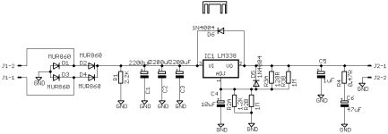
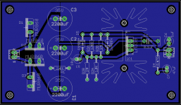
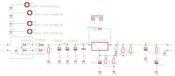
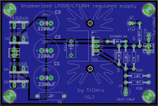
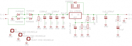
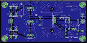
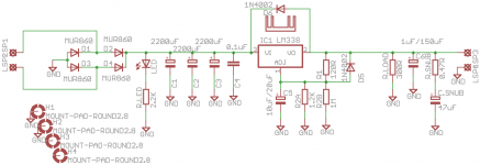
I've attached the schematic I've used and the pcb layout with autorouter
p.s. I'm planning on using Panasonic FR for main reservoir capacitors. I don't think that I want to bypass them with smaller ones.
I'm planning on doing a lm338 snubberized power supply. I want to use it for a ta2020 amp and another one for a tda7297 amp. I guess the supply voltage should be about 13.5V and 16V respectively.
I made the schematic in Eagle but I got lost at pcb layout. I haven't done any pcb and I don't know what's best as far as parts layout, spacing, trace width etc. I plan on making it myself with one of the few methods available so I'm looking for a single sided pcb. Also I want to add the option of two parallel resistors for the resistors that set the voltage for lm338. I guess it's nice to have the option of dialing the voltage as close as possible. I'm planning on using the to-220 version. Also at this moment I'm oscillating between lm338 and lt1084. Current requirement is about 2-3A maximum so any should do. The LT1084 needs a 22uF tantalum or 150uF electrolytic on the output as that's part of the frequency compensation network. I guess a 5mm lead spacing on that capacitor would enable me to add either a 1uF tantalum for lm338 either 22uF tantalum or 150uF electrolytic.
I don't care about it being super miniaturized. I prefer to limit the capacitor's exposure to heat (if any) from the heatsink. Also I saw some versions with a transistor somewhere on the adjust pin, any idea what that's used for? I'd modify the schematic for nicer functions
Also I want to use TO-220 MUR860 diodes, do they need any kind of heatsink? I can add the small ones directly on them, or else space them out more to make room for larger individual heatsinks?
So basically I'd like some help from anyone willing, with the schematic/pcb layout.
I've attached the schematic I've used and the pcb layout with autorouter
p.s. I'm planning on using Panasonic FR for main reservoir capacitors. I don't think that I want to bypass them with smaller ones.
Attachments
No one?
I'm thinking this to be for everyone who wants to make one at home, single sided. I haven't seen any pcb layout for LM338, with MUR860 diodes and parallel resistors.
I've also seen some layouts with most of the copper on the circuit itself, there were only small lines delimiting the traces themselves. Is that a better way to design a power supply pcb?
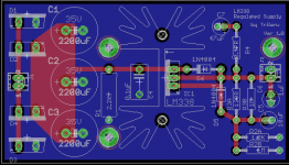
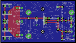
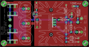
I've made some changes. I also added power planes. Is this good?
edit:
I'd like to connect the heatsink's pins to the ground plane, and also the holes in the corners, I want to ground them at install.
edit:
I'd like to connect the heatsink's pins to the ground plane, and also the holes in the corners, I want to ground them at install.
Attachments
Last edited:
I've added pads to the corner holes so I can ground them with the case, but I don't know how to add solder pads to the heatsink pins. I wish to ground it as well. Also for mechanical security.
This design can be used by anyone besides commercial purposes
Any feedback? Did I do something wrong here?
edit:
I've tried connecting the heatsink to ground in the schematic but I can't, the wire won't "stick" to it Like it has no electrical connection.
This design can be used by anyone besides commercial purposes
Any feedback? Did I do something wrong here?
edit:
I've tried connecting the heatsink to ground in the schematic but I can't, the wire won't "stick" to it
Like it has no electrical connection.Attachments
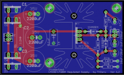
I also did a two layer version.
I also tried to get it as small as possible.
There are only three mounting holes, but they are aligned and should hold the board in place. I think I might try a pcb making service for this one.
Everyone can use them for personal purposes, not for commercial use.
I accept any suggestions regarding both versions.
I'm planning on using them somewhere in the area of 13-16V output at about 3A maximum 4A.
Attachments
Hi Trileru,
Looking at the schematic I found two 1 Meg resistors which puzzled me. But perhaps you can enlighten me...
Both are parallel to other resistors (120 Ohms and 1k2 Ohms). But since resistors are notorious sources of noise I doubt their use in this schematic. On the other hand I might have missed their relevance.
Regards,
Edwin
Hello Edwin,
I put those resistors there so you can use another one in parallel to dial in the voltage as close as possible to your needs. I just noted it 1M as that would keep the total value close to the other resistor. For me I would just use whatever resistor needed in place for 1M to dial in the voltage. Same goes for both voltage divider resistors. Although it's recommended to use 120ohm resistor for R3, one could use a slightly lower/higher value to get the desired result. I guess if you don't want to use two resistors you could leave that spot unconnected.
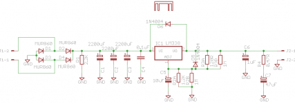
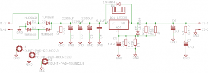
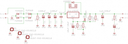
I made a small revision by replacing C5 with a larger pin spacing for both variants. Also I've adjusted the silkscreen notations by adding the LT1084 possibility.
The schematic is almost the same but in some cases C5 is called at 20uF and the output capacitor needs to be 150uF electrolytic or 22uF tantalum. The footprint should match any I think.
Also for diodes 1N4002 can be used, I just didn't find them in the library, and also IC1 is not actually a LM338 in the eagle schematic, but something else in the same package. It was the only one I found that had a vertical mounting position for pcb layout. That shouldn't matter as I kept the package integrity.
I put those resistors there so you can use another one in parallel to dial in the voltage as close as possible to your needs. I just noted it 1M as that would keep the total value close to the other resistor. For me I would just use whatever resistor needed in place for 1M to dial in the voltage. Same goes for both voltage divider resistors. Although it's recommended to use 120ohm resistor for R3, one could use a slightly lower/higher value to get the desired result. I guess if you don't want to use two resistors you could leave that spot unconnected.
I made a small revision by replacing C5 with a larger pin spacing for both variants. Also I've adjusted the silkscreen notations by adding the LT1084 possibility.
The schematic is almost the same but in some cases C5 is called at 20uF and the output capacitor needs to be 150uF electrolytic or 22uF tantalum. The footprint should match any I think.
Also for diodes 1N4002 can be used, I just didn't find them in the library, and also IC1 is not actually a LM338 in the eagle schematic, but something else in the same package. It was the only one I found that had a vertical mounting position for pcb layout. That shouldn't matter as I kept the package integrity.
Attachments
I tried to make the last thing that bugged me, add solder pads to the heatsink holes. But I ended up in trouble at DRC check with heatsink's hole size not matching the pad's hole size etc.
I would need some assistance with this problem. What can I do so I can solder the heatsink's pins to ground?
I would need some assistance with this problem. What can I do so I can solder the heatsink's pins to ground?
If mechanics are an issue, you can make holes and pads to solder the pins; just don't have them connect to anything.
Looking back over things...
I don't know what purpose R1 serves. I'd remove it, and remove R3B. Using 120Ω at R3 provides a good idle load for the regulator.
Looking back over things...
I don't know what purpose R1 serves. I'd remove it, and remove R3B. Using 120Ω at R3 provides a good idle load for the regulator.
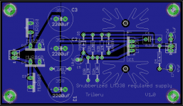
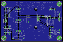
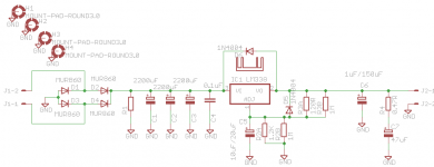
I've removed R3B in this version, and also made the single sided board smaller so it fits 5cmx10cm. Also I moved some capacitors further from the heatsink.
How can I make the isolated pads on the heatsink?
edit:
I just realized that I must note +/GND on the output connector, as they are reversed from single sided to double sided. So if anyone plans on doing the boards please measure before connecting the output of the board.
How can I make the isolated pads on the heatsink?
edit:
I just realized that I must note +/GND on the output connector, as they are reversed from single sided to double sided. So if anyone plans on doing the boards please measure before connecting the output of the board.
Attachments
Last edited:
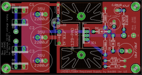
I've made some changes to the double sided board.
I've been reading some more and found a discussion regarding LT1085. Some people have found that larger (330uF) ADJ capacitor gave better results so I increased the footprint of this capacitor and the output capacitor just to be safe. Also I've rearranged some output components. I've removed completely the input/output connectors as I'm probably going to solder my cables directly to the board.
The ta2020 has it's own power reservoir caps (also bypassed with lower values, but I'm going to test this as well). Is it worth to add a 0.1uF film cap on the output of this regulator as well? I guess I do have some space left there, especially if I remove the snubber
I've added R.LOAD resistor of 300 ohm that will serve as a load for the regulator. Should keep it at 45-55mA in my 13.5V-16V range. I moved the LED on the input side of the regulator. I could have moved the positive connection hole next to the negative one but I prefer the trace as short as possible.
Also I am not yet sure about the reservoir caps, should I leave all three or better a larger one and a smaller one? Something like 6800uF and 100uF.
Attachments
Your circuit doesn't need R.LOAD.
The regulator will impress a 1.25V reference voltage across R1. Ohm's Law then says that will be a little over 10mA flowing through R1. That current also flows through the specified R2 value to set the desired regulated output voltage. The point is, that 10mA is already an adequate idle current for the regulator.
I am glad to see you add a series LED to your bleeder resistor. The voltage on the filter caps should be only about 18VDC; is bleeding the charge really necessary?
The ADJ capacitance? I can't quite put my finger on it, but I recall there being the possibility of performance degradation with over-sized caps used there. I think 47μF is the upper limit. I can't recall where I got this info, though. NatSemi app notes, perhaps.
I've put that load resistor as someone on another forum asked me if there's enough current flowing to keep the regulator stable if no load is present so I wanted to make sure. Also it seems to keep the regulator into a more linear zone if there's no load.
Also I've skimmed through this topic: http://www.diyaudio.com/forums/powe...ok-lm317-lm337-regulators-16.html#post1902476
And it seems they got the best results with adj capacitor of 330uF, but also they are using a LT1085, which should be similar to LT1084 that I'm also planning to test on this board.
I'm only trying to keep options open. I may decide to not solder some components, but I like the idea of it being able to be used with more regulators (LM317, LM337, LT1084, LT1085 etc).
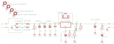
I now have a few issues left. One of them is if I keep three reservoir capacitors or should I use two different sizes ? I'm currently thinking of putting a 4700uF and something like 1000uF or 470uF. The other problem is that I cannot solder the pins of the heatsink. If I use another similar heatsink that has electrical connection on it's pins and I ground it, it does a weird thing and it clears the copper around it's outline (and inside the footprint). I've attached a picture to get an idea.
Also I've skimmed through this topic: http://www.diyaudio.com/forums/powe...ok-lm317-lm337-regulators-16.html#post1902476
And it seems they got the best results with adj capacitor of 330uF, but also they are using a LT1085, which should be similar to LT1084 that I'm also planning to test on this board.
I'm only trying to keep options open. I may decide to not solder some components, but I like the idea of it being able to be used with more regulators (LM317, LM337, LT1084, LT1085 etc).
I now have a few issues left. One of them is if I keep three reservoir capacitors or should I use two different sizes ? I'm currently thinking of putting a 4700uF and something like 1000uF or 470uF. The other problem is that I cannot solder the pins of the heatsink. If I use another similar heatsink that has electrical connection on it's pins and I ground it, it does a weird thing and it clears the copper around it's outline (and inside the footprint). I've attached a picture to get an idea.
Attachments
I've put that load resistor as someone on another forum asked me if there's enough current flowing to keep the regulator stable if no load is present so I wanted to make sure. Also it seems to keep the regulator into a more linear zone if there's no load.
Hello there
...You're right about including a min. current draw (about 100mA) at the regulator output, you could either use a load resistor or a LED.
Also I've skimmed through this topic: http://www.diyaudio.com/forums/powe...ok-lm317-lm337-regulators-16.html#post1902476
And it seems they got the best results with adj capacitor of 330uF, but also they are using a LT1085, which should be similar to LT1084 that I'm also planning to test on this board.
I'm only trying to keep options open. I may decide to not solder some components, but I like the idea of it being able to be used with more regulators (LM317, LM337, LT1084, LT1085 etc).
Here 're a quote from the national datasheet....
That gives a pretty good idea about the value of the adjustment bypass capacitor and that its performance depends more on the capacitor type.The adjustment terminal can be bypassed to ground on the LM138 to improve ripple rejection. This bypass capacitor prevents ripple from being amplified as the output voltage is increased. With a 10 μF bypass capacitor 75 dB ripple rejection is obtainable at any output level. Increases over 20 μF do not appreciably improve the ripple rejection at frequencies above 120 Hz. If the bypass capacitor is used, it is sometimes necessary to include protection diodes to prevent the capacitor from discharging through internal low current
paths and damaging the device.
In general, the best type of capacitors to use are solid tantalum. Solid tantalum capacitors have low impedance even at high frequencies. Depending upon capacitor construction, it takes about 25 μF in aluminum electrolytic to equal 1 μF solid tantalum at high frequencies. Ceramic capacitors are also good at high frequencies; but some types have a large decrease in capacitance at frequencies around 0.5 MHz. For this reason, 0.01 μF disc may seem to work better than a
0.1 μF disc as a bypass.
The other problem is that I cannot solder the pins of the heatsink. If I use another similar heatsink that has electrical connection on it's pins and I ground it, it does a weird thing and it clears the copper around it's outline (and inside the footprint). I've attached a picture to get an idea.
You need to route the ground connection to the heatsink (the yellow wire)
.Best regards.
If I route it it is ok, but I wanted it to go on the ground plane, and not clear the ground plane around it. That way it was easier and I had a hefty ground plane in that area. Even so I might route it to the nearest ground connection, and use that vertical area to separate the ground plane from the input side from the ground plane of the output side, and just use the lower connection to complete the circuit between both ground planes. As I read that is good practice as it keeps the noise out from the output area ground.
- Status
- This old topic is closed. If you want to reopen this topic, contact a moderator using the "Report Post" button.
- Home
- Amplifiers
- Chip Amps
- LM338 power supply pcb, I want to make on for personal use