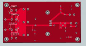
If I route it it is ok, but I wanted it to go on the ground plane, and not clear the ground plane around it. That way it was easier and I had a hefty ground plane in that area. Even so I might route it to the nearest ground connection, and use that vertical area to separate the ground plane from the input side from the ground plane of the output side, and just use the lower connection to complete the circuit between both ground planes. As I read that is good practice as it keeps the noise out from the output area ground.
You mean like this?
An externally hosted image should be here but it was not working when we last tested it.
Yes, that's an older version and I had the ground plane on the bottom.
I attached a picture, I guess it will work like this? What you did is what I wanted, but with the ground plane on the top side. That heatsink that I used previously didn't have electrical connection. And had no problem with having the power plane on the bottom side. But this heatsink has also solder pads and it seems it clears the copper on it's footprint.
I attached a picture, I guess it will work like this? What you did is what I wanted, but with the ground plane on the top side. That heatsink that I used previously didn't have electrical connection. And had no problem with having the power plane on the bottom side. But this heatsink has also solder pads and it seems it clears the copper on it's footprint.
Attachments
I don't get something. Before I've used SK129 and now I'm using SK129-PAD. Are they both heatsinks? Or is one a heatsink and the other is the pads for the first heatsink? In which case do I need to put them one on top of the other? Or do I install the pad on the back of the board? But how do I do that?
I will never draw more than 3A, and usually below 2A for sure. At 0.7V per diode at 2A that's 1.4W. I guess they are able to give off that heat with no heatsink attached? I'd rather not disturb the feng shui of the arrangement
Good luck then and looking forward to see the finished board
.Good luck then and looking forward to see the finished board
Thank you!
Hope I finish it in a way that I'm satisfied. Also I want to have some options on it like snubber etc so I make some measurements of my own.
I attached a picture. With the pads installed, if I connect them to ground I can see that the trace is not removed from it's center, like it does not have holes there.
edit:
nah, ignore this message, all of the holes are like that. I wasn't sure that pads have holes actually but I guess they must have.
Attachments
Last edited:
I don't get something. Before I've used SK129 and now I'm using SK129-PAD. Are they both heatsinks? Or is one a heatsink and the other is the pads for the first heatsink? In which case do I need to put them one on top of the other? Or do I install the pad on the back of the board? But how do I do that?
Both are heatsinks the first one without the soldering pads and the other with the pads. Your top layer where the regulator and its heatsink resides is the layer with the ground plane am i right?
If i am right how are u gonna solder the heatsink legs (through hole) to the top layer with no clearance between its body and the board?
I don't know about u but i am sleep deprived at the moment so may be i am not seeing things right.
The top red layer is the ground plane yes.
Well, the heatsink has two pins, and I guess the solder pads are on both sides right? I'm thinking of soldering them on the bottom side, I can't solder them on top as the heatsink would cover those. I really don't know how to make sure that the pads are on the bottom or/and on the bottom. The holes of the heatsink has pads, that are electrically connected on both sides so why would that be a problem?
edit:
I will have to isolate the regulator from the heatsink, that's for sure.
The top red layer is the ground plane yes.
Well, the heatsink has two pins, and I guess the solder pads are on both sides right?
Nope...the solder pads are on one side only...that's the side opposite to which the actual component are...unless you installed the heatsink on both layers.
Yeap, sure.
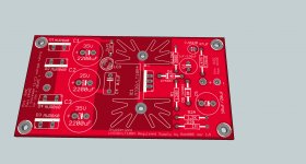
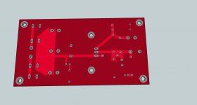
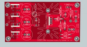
I also exported the project in SketchUp And as I see it, there's pads on both sides. At least they look like all the other pads. Back when I had no pads on the first heatsink I could clearly see that there were no pads, only holes.
I also exported the project in SketchUp
And as I see it, there's pads on both sides. At least they look like all the other pads. Back when I had no pads on the first heatsink I could clearly see that there were no pads, only holes.Attachments
Is that what you need?
An externally hosted image should be here but it was not working when we last tested it.
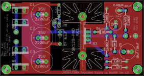
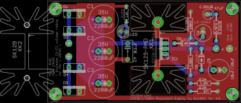
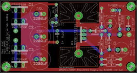
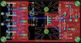
Yes, like that, only that I want to separate the ground planes between the input and the output of the regulator. I wanted to have a smaller separation something like and earlier version. I really don't mind it the way I have it now in the final version. Its seems pretty good now. Also I think that the pads are on both sides as I saw from the rendering and also I might extract the gerber files so I'm sure. Other than that.... I guess it looks just about ready for production. I still ponder on the main caps. This way I have more capacitance and I can get Panasonic FR caps there. If I decide to put one larger and one smaller I will have to go for other cap brand and I will need to search for availability and dimension specs. 2200uF/35V are largest on Panasonic FR and they are affordable.
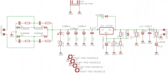
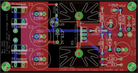
As an Eagle exercise I've made a version with snubbers on the rectifying diodes. I've used a capacitor and resistor in series for each diode. I mounted them on the backside of the board, so if anyone wants to do this board and don't want the bottom silkscreen pay attention to the mounting holes.
I added some pictures and Eagle files.
Must read some more on those main capacitors to see what route I'm taking in the end. Board looks good and I guess after I settle with those capacitors I will send it for production I guess I'll stick with the main one, not with the one with snubbers on diodes.
I'm going to sleep
I added some pictures and Eagle files.
Must read some more on those main capacitors to see what route I'm taking in the end. Board looks good and I guess after I settle with those capacitors I will send it for production
I guess I'll stick with the main one, not with the one with snubbers on diodes.I'm going to sleep
Attachments

I guess I'm gonna be outnumbered, but on my way out...
If it is fervently believed that the regulator needs a higher idle current, just reduce the value of R1. You don't need to add more resistors or more LEDs. In this application, at least, I doubt that it will make the least bit of difference. Goodnight.
If it is fervently believed that the regulator needs a higher idle current, just reduce the value of R1. You don't need to add more resistors or more LEDs. In this application, at least, I doubt that it will make the least bit of difference. Goodnight.
- Status
- This old topic is closed. If you want to reopen this topic, contact a moderator using the "Report Post" button.
- Home
- Amplifiers
- Chip Amps
- LM338 power supply pcb, I want to make on for personal use