Hi,
I have bought this amp from ebay LM1875T 30W 30 w Stereo Amplifier Board Perfectly Compatible with TDA2030A | eBay
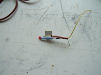
I connected it to 2x12vac transformer and used a small heatsink. the problem is that it gets very hot even if I don't use any input signal. According to the spec it should have 100 mA max so with 26 V rail to rail I would not expect it to get so hot. Anyone has an idea?
I have bought this amp from ebay LM1875T 30W 30 w Stereo Amplifier Board Perfectly Compatible with TDA2030A | eBay
I connected it to 2x12vac transformer and used a small heatsink. the problem is that it gets very hot even if I don't use any input signal. According to the spec it should have 100 mA max so with 26 V rail to rail I would not expect it to get so hot. Anyone has an idea?
Try shorting the input signal to ground.
Then try building a little RF detector with a 100nF capacitor, a 10K resistor and an LED.
This will detect if the circuit is oscillating. You might need to play with the values a bit.
You connect the detector where the speaker would connect.
Then try building a little RF detector with a 100nF capacitor, a 10K resistor and an LED.
This will detect if the circuit is oscillating. You might need to play with the values a bit.
You connect the detector where the speaker would connect.
Attachments
Last edited:
I have a bad idea. The series TDA2030, TDA2040, TDA2050, LM1875, are all pin compatible. I see two possibilities.
1) Someone is counterfeiting chips and doing a bad job of it. They could get away with the crappy chips if they were used in a 12V single ended supply design. Most of the fall out like you noticed seems to happen when you increase the supply voltage to anything near what they are supposed to run at.
2) Someone is getting chips that failed testing and labeling them TDA2030, TDA2040, TDA2050, LM1875, and selling them on the gray market.
IMNSHO: When it looks too good to be true, it isn't. The suppliers of these kits can't be using real chips. If you have a lot of time, you may want to read through
http://www.diyaudio.com/forums/chip-amps/177717-2-1-tda2030-amp-ebay.html
My solution was to replace the chips with ones from jameco.com and another user found replacements at Radio Shack that worked. I'm not sure Radio Shack still carries them as I have tried their web site and they weren't listed. It would cost just over $6 plus shipping to get the Jameco parts if you don't have another supplier.
The ones I got from Jameco seem to be good. At idle/no volume they are barely above ambient temperature. At high volume, probably 10-15 Watts output, they get extremely hot, too hot to touch, with a heatsink!
The amps are still a good deal if you replace the chips with good ones. Trick is finding good ones.
It's not a good idea to run any semiconductor too hot to touch. You should ideally use the 5 second rule. If you can touch it for 5 seconds then it is hot but not too hot.
Any hotter and you will seriously degrade the life expectancy of the device - BIGGER heatsnk.
There is of course a limit to how much heat can be transferred away from the device that even a giant heatsink can't improve upon.
Any hotter and you will seriously degrade the life expectancy of the device - BIGGER heatsnk.
There is of course a limit to how much heat can be transferred away from the device that even a giant heatsink can't improve upon.
Yes, from data sheet:
"The LM1875 must always be operated with a heat sink,
even when it is not required to drive a load.
The maximum idling current of the device is 100 mA..."
If you have a resistor at 260 ohms (rated for 5W) and put 26V on it, how hot will it get?
Maybe a bigger heatsink is all that is needed.
")
"The LM1875 must always be operated with a heat sink,
even when it is not required to drive a load.
The maximum idling current of the device is 100 mA..."
If you have a resistor at 260 ohms (rated for 5W) and put 26V on it, how hot will it get?
Maybe a bigger heatsink is all that is needed.
Last edited:
Yes, from data sheet:
"The LM1875 must always be operated with a heat sink,
even when it is not required to drive a load.
The maximum idling current of the device is 100 mA..."
If you have a resistor at 260 ohms (rated for 5W) and put 26V on it, how hot will it get?
Maybe a bigger heatsink is all that is needed.
Thank you all for the responses.
1. I do have an osciloscope so soon as I have some time I will connect and see if it oscilates. Personally I don't believe it does since I see 0 DC and AC (with DVM).
2. According to my calculations, the heatsink should dissipate no more than 5.2 Watts (with no output power) and I can tell you - no way it is how like 5W.
I tend to agree that these chips are poor/fake
I am using heat sinks. One on each LM1875 attached with an aluminum pop rivet.
No fan, just free air allowing for convection. It may perform better if I stick it in a box with vent slots such that air flow impinges directly on the vanes.
If you look at the specs for the device, printed on the reverse side of the package, it maxes out at ~5 Watts with a 50 degree Centigrade rise over ambient => assuming room temperate of about 24 C degree then 74 C<scalding hot *BUT* still within limits> would be expected assuming the amp is ~25% efficient and putting out near the max 20 Watts.
An externally hosted image should be here but it was not working when we last tested it.
No fan, just free air allowing for convection. It may perform better if I stick it in a box with vent slots such that air flow impinges directly on the vanes.
If you look at the specs for the device, printed on the reverse side of the package, it maxes out at ~5 Watts with a 50 degree Centigrade rise over ambient => assuming room temperate of about 24 C degree then 74 C<scalding hot *BUT* still within limits> would be expected assuming the amp is ~25% efficient and putting out near the max 20 Watts.
Those heatsinks are too small. The spec on the package as you stated it is 50°C/5W, so then, it is a 10°C/W heatsink.
With +/- 26 V rails (52 V total supply), and with the quiescent/idle current of 100 mA, the dissipation is 5.2 W. Temp will rise 52°C above ambient with that little heatsink, so about 77° (at 25°), which is to hot to touch. Even if you mean 26 V total supply (+/-13 or just 26 V single) then it will rise 26° above ambient, so about 51°. That will feel HOT but you should be able to hold your finger to it. That is without any output whatsover.
Do your math again, If the amp is 25% efficient and putting 20 W into the speaker... it is dissipating 60 W as heat, not 5 W! (80 W total * 25% = 20 W output). Actually the LM1875 can only dissipate just over 30W before thermal shutdown when used with a 1°C/W heatsink (including the insulator if used).
Those heatsinks are too small. The spec on the package as you stated it is 50°C/5W, so then, it is a 10°C/W heatsink.
With +/- 26 V rails (52 V total supply), and with the quiescent/idle current of 100 mA, the dissipation is 5.2 W. Temp will rise 52°C above ambient with that little heatsink, so about 77° (at 25°), which is to hot to touch. Even if you mean 26 V total supply (+/-13 or just 26 V single) then it will rise 26° above ambient, so about 51°. That will feel HOT but you should be able to hold your finger to it. That is without any output whatsover.
Do your math again, If the amp is 25% efficient and putting 20 W into the speaker... it is dissipating 60 W as heat, not 5 W! (80 W total * 25% = 20 W output). Actually the LM1875 can only dissipate just over 30W before thermal shutdown when used with a 1°C/W heatsink (including the insulator if used).
Those heat sinks are fine. I made a typo, I meant to say 75% efficient and got ahead of myself to the 25% waste part.
Big hint, less caffeine.
With the exception of the typo, all my numbers are accurate. I am running it on a +-17 V supply.
If you go to the LM1875 data sheet, you will find my Device Dissipation vs Ambient Temperature, expected power output, everything is well within the graphs given those heat sinks, safe operating temperature, power supply.
LM1875T 30W 30 w Stereo Amplifier Board Perfectly Compatible with TDA2030A | eBay
From the listing "Power Supply: Dual AC9-16V recommended dual AC15V."
The eBay seller is probably hopelessly optimistic of getting 30 Watts out of that system but I have seen stranger things. Probably means 20 Watts of music and 10 Watts of keeping your room warm.
While the 25% efficiency typo is obviously my fault, you are kind of pulling numbers out of the air. I mean 52 V on a amp that has a recommended 30 VAC transformer?
Do you understand what I am saying? I mean if I wanted to pull numbers out of thin air I could go just as far the other way and say run the amp on +-10 Volts. Kind of trying to stick to reality here.
I connected it to 2x12vac transformer and used a small heatsink. the problem is that it gets very hot even if I don't use any input signal. According to the spec it should have 100 mA max so with 26 V rail to rail I would not expect it to get so hot. Anyone has an idea?
Do you have heatsinks on the chips? 100mA at 26 Volts is 2.6 Watts. Without a heatsink it would be HOT - and be normal.
From the data sheet page 7
POWER DISSIPATION AND HEAT SINKING
The LM1875 must always be operated with a heat sink, even
when it is not required to drive a load. The maximum idling
current of the device is 100 mA, so that on a 60V power
supply an unloaded LM1875 must dissipate 6W of power.
The 54°C/W junction-to-ambient thermal resistance of a
TO-220 package would cause the die temperature to rise
324°C above ambient, so the thermal protection circuitry will
shut the amplifier down if operation without a heat sink is
attempted.
It's very common to underestimate the required heatsink.
G²
One more time, these amps are not made nor recommended by the vendor to run at anything near 52-60V!!! The filter capacitors in the power supply of the ones I've seen are only rated at 25 V!!! If you put 30V at a couple of amps on the rails, the least of your worries will be device heat dissipation.
The 100 mamps, something that I am sure elic understands but I wonder if anybody else does, is the DROP DEAD WE WILL NOT SELL DEVICES THAT EXCEED THIS limit. The typical for a LM1875 is 70 mamps. Context of his post is his chips heat up worse then the worse case scenario.
So you have a typical of 70 mamps running off ~30 V or 2.1 Watts. This is Christmas tree light kind of heat. Trivial, non consequential.
The manufacturers data also makes no allowances for soldering the device to a copper clad circuit board. It is as if they are taking the worse case scenario of using wire wrap and suspending the device above the circuit board. This is inconsistent with reality and many other National Semiconductor references. A good example is the LM379 which is a 6+6 or 12 Watt stereo chip.
Their recommended layout for this chip<LM377 too?> was to just use a double sided circuit board and solder the ground pins to top side of board. They also came out with a version where the middle legs were tabs/wings that could be soldered to the circuit board with no heat sink.
At these voltages the LM1875 puts out no where near 30 Watts. At idle they are no where near 6 Watts. My information on a TO220 package, any package including amps, transistors, and regulators, is they are capable of dissipating ~5 Watts when soldered to a copper clad board. I have never had reason to dispute this.
The 100 mamps, something that I am sure elic understands but I wonder if anybody else does, is the DROP DEAD WE WILL NOT SELL DEVICES THAT EXCEED THIS limit. The typical for a LM1875 is 70 mamps. Context of his post is his chips heat up worse then the worse case scenario.
So you have a typical of 70 mamps running off ~30 V or 2.1 Watts. This is Christmas tree light kind of heat. Trivial, non consequential.
The manufacturers data also makes no allowances for soldering the device to a copper clad circuit board. It is as if they are taking the worse case scenario of using wire wrap and suspending the device above the circuit board. This is inconsistent with reality and many other National Semiconductor references. A good example is the LM379 which is a 6+6 or 12 Watt stereo chip.
An externally hosted image should be here but it was not working when we last tested it.
Their recommended layout for this chip<LM377 too?> was to just use a double sided circuit board and solder the ground pins to top side of board. They also came out with a version where the middle legs were tabs/wings that could be soldered to the circuit board with no heat sink.
At these voltages the LM1875 puts out no where near 30 Watts. At idle they are no where near 6 Watts. My information on a TO220 package, any package including amps, transistors, and regulators, is they are capable of dissipating ~5 Watts when soldered to a copper clad board. I have never had reason to dispute this.
LM379...interesting.
ftp://ftp.eskimo.com/home/mzenier/LM379.pdf
Data sheet has 2 x 6W output dissipating about 14W.
Another graph shows that you would need more than 100 square inches of 1/8" aluminum heat sink for this.
I think that is a little more than "...to just use a double sided circuit board and solder the ground pins to top side of board..."
IMHO
But back to the subject.
1. The original poster wanted to know why his devices were getting hot.
2. The original poster posted a pix of the heat sink he was using.
3. Myself and others suggested getting a larger heat sink.
The original poster can try that or not.
The original poster may let us know the results.
More later but TV is calling me.
LM379...interesting.
ftp://ftp.eskimo.com/home/mzenier/LM379.pdf
Data sheet has 2 x 6W output dissipating about 14W.
Another graph shows that you would need more than 100 square inches of 1/8" aluminum heat sink for this.
I think that is a little more than "...to just use a double sided circuit board and solder the ground pins to top side of board..."
IMHO
But back to the subject.
1. The original poster wanted to know why his devices were getting hot.
2. The original poster posted a pix of the heat sink he was using.
3. Myself and others suggested getting a larger heat sink.
The original poster can try that or not.
The original poster may let us know the results.
More later but TV is calling me.
1) Accurate
2) No, I posted a summary of my finding and results. These were collaborated in the cross referenced thread where another user reported his amp was drawing 2 amps on the rails from a bench power supply at idle. i.e pulling 48 Watts at no volume. I'd have to recheck this with the poster, could have been 2 amps total. At least 200 times what the specifications call for and maybe 400 times. From memory since I have a busy day ahead, he was only using 12 V rails.
2a) You and at least one other user posted ~no heat sink and voltages near the chip maximum, you would expect heating.
2b) I posted the pictures of my heat sinks and said that the assumption of no heat sinks was not accurate and I was running no where near the maximum voltage for the chip. I also corrected myself with regards to an error in efficiency.
I also posted a new link to the eBay ad since the first one had expired.
3) Accurate.
Yes, I have am using a heatsink that I took from an old PC. There is absolutely no way that 5.2W will make it too hot to touch. The heatsink is about 8 x 3 cm and it has many sides (I mean a log of effective surface). I hope to connect a scope today and see if there are any oscilations.
Hi. Do you have the eBay item number, without posting a link to it?
The link at post 1 doesn't work due to eBay Rover error. By the way, you can edit post 1.
I'd like to see the circuit board and schematic, in order to make a guess about why the chip is doing extra work at idle. The schematic would help--the exact schematic.
The link at post 1 doesn't work due to eBay Rover error. By the way, you can edit post 1.
I'd like to see the circuit board and schematic, in order to make a guess about why the chip is doing extra work at idle. The schematic would help--the exact schematic.
you are kind of pulling numbers out of the air. I mean 52 V on a amp that has a recommended 30 VAC transformer?
You DO realize that a 30VAC transformer provides 42V DC PLUS regulation overage when at idle, in addition to mains variations, right? Say 8% regulation and you're at just over 45V, and then you have mains variations on top of that. Not very far from 52V. In addition, the LM1875 IS rated at 60V maximum, 52V is a safe distance from that value.
elic said:I connected it to 2x12vac transformer and used a small heatsink. the problem is that it gets very hot even if I don't use any input signal. According to the spec it should have 100 mA max so with 26 V rail to rail I would not expect it to get so hot. Anyone has an idea?
2x12VAC does not give 26V rail to rail, it gives 33.6V rail to rail.
You DO realize that a 30VAC transformer provides 42V DC PLUS regulation overage when at idle, in addition to mains variations, right? Say 8% regulation and you're at just over 45V, and then you have mains variations on top of that. Not very far from 52V. In addition, the LM1875 IS rated at 60V maximum, 52V is a safe distance from that value.
2x12VAC does not give 26V rail to rail, it gives 33.6V rail to rail.
No I don't and it doesn't when connected to a circuit providing a reasonable load. This circuit when working properly should draw about 4-5 Watts at idle which is more then enough. My power rails are at 18 V at idle.
- Status
- This old topic is closed. If you want to reopen this topic, contact a moderator using the "Report Post" button.
- Home
- Amplifiers
- Chip Amps
- lm 1875 quicent current too high