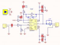
i've brought lm3886 pcbs, just right start the soldering job, but before that, i wish to double check if this schematic has missing something and any flaws on it. May some experts give any ideas before i start soldering?
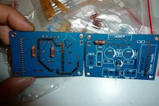
btw, is that ok to use a CFM60 1watt resistor? (i saw others mostly use 1/4w)
Any advice/comments are apperciate.


btw, is that ok to use a CFM60 1watt resistor? (i saw others mostly use 1/4w)
Any advice/comments are apperciate.
1 watt resistors are fine as long as not to bulky.
I would question the omission of a zobel network, a 0.1uf and 10 ohm connected in series and fitted from amplifier output (pin 3) to the speaker ground return point. For most amps that is a must for stability.
When you power the amp up I would suggest a bulb tester (search the forums for that )
)
I would question the omission of a zobel network, a 0.1uf and 10 ohm connected in series and fitted from amplifier output (pin 3) to the speaker ground return point. For most amps that is a must for stability.
When you power the amp up I would suggest a bulb tester (search the forums for that
1 watt resistors are fine as long as not to bulky.
I would question the omission of a zobel network, a 0.1uf and 10 ohm connected in series and fitted from amplifier output (pin 3) to the speaker ground return point. For most amps that is a must for stability.
When you power the amp up I would suggest a bulb tester (search the forums for that)
the resistor is too bulky, decide to solder on the back side of the board.
sorry to bring up two beginner questions, just googled:
1) zobel network with a 0.1uf or 0.1uh? i saw others have a copper coil pack at the output.
2) i had a ready made powersupply board, comes with recifitier and DC output protection using upc1237ha chip. Do i still need the zobel network?
An externally hosted image should be here but it was not working when we last tested it.
It's no problem 
The zobel is a cap plus resistor. 0.1uf is typical. The zobel network gives a defined "termination" to the amplifier output. Many amplifiers would just oscillate and self destruct without.
Sometimes a coil is used too and this always goes after the zobel network. The circuit you have looks an absolute basic bare bones implementation.
Also a small (say 22 pico farad) might also be used across the feedback resistor.
Have you looked at the data sheet for the IC ? There is a "single rail" circuit in there that shows all these features.
Here is the data sheet, look at fig 2. In fact the zobel recommended there is 2.7 ohm and 0.1 uf and 50pf cap in series with a resistor over the feedback resistor. It also includes an output coil (which is just half a dozen turns of copper wire, air spaced, no former).
Attachments
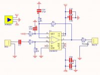
Yeah, the output is still wrong. You have 10R in parallel with 0.1uF, in series with the output. For that part, the cap should be an inductor (coil). But completely missing is the RC from output to ground; 2.7 Ohms in series with 0.1 uF from ouput pin to load ground return point.
Also, the 100 uF caps from the power pins to ground should be at least 470 uF, according to the text in the datasheet. And in parallel with those caps, you don't show the mandatory 0.1 uF from each power pin to ground, which should be connected right at each power pin, with the shortest-possible path to ground.
And many people make CD1 much larger, saying they otherwise are unhappy with the bass output.
Last edited:
RF filtering, I google around found something similiar.
Is that mean a 220pf connect between pin9 and pin10?
Added Feedback(in blue), removed.
Power pins to ground: i can change to 470uf or larger.
Output Zobel: i saw others here , said is a copper coil windings?
As a middle-age bloke, which has fail his physics exams 20 years ago, I've tried very much to understand the technical terms on learning this chip amp. (i've never build something like this.)
May please check, if i have done it right?
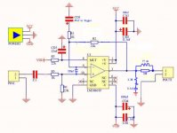

Output Zobel looks good now.
You can use 220 pF as you have shown, instead of a C in parallel with the 22k. But I read something recently that gave a reason to not do it that way. It will be minor. Maybe try it both ways, later, after everything else is working.
You will probably still need a low-pF cap in parallel with the feebback R.
Looks like your getting there 
The 220pf I would question. It increases the "noise gain" of the amp coming into play at higher frequencies. Its a valid technique but I'd say it was a bit more involved than just adding a cap and hoping for the best.
In essence it is similar to this,
http://www.diyaudio.com/forums/analog-line-level/196461-different-opamp-compensation-technique.html
I would stick to a small cap across the feedback resistor, nothing nore than 22pf ish initially.
thanks gootee & Mooly for your help.
For the zobel copper coil windings & zobel resistor:
what value "uh" do i require?
will 10R 1/4w combine with the coil?
I don't have this item in my bin so i will order it from RS components.
The 220pf is ceramic material, am i right? Will a mica work at this position?
For parallel a C with 22k on feedback, which i read on datasheet.
In series with a resistor (Rf2) will it eliminate ringing? Does Rf2 value has to be the same to Rf1?
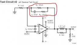
Mooly:
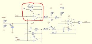
I've read your Opamp Compensation Technique. I had a DAC kit (this one, modify version by same designer), the opamp ad797 as i/v also have similar design(in red circle). Similar techniques on chip amps?
For the zobel copper coil windings & zobel resistor:
what value "uh" do i require?
will 10R 1/4w combine with the coil?
I don't have this item in my bin so i will order it from RS components.
The 220pf is ceramic material, am i right? Will a mica work at this position?
For parallel a C with 22k on feedback, which i read on datasheet.
In series with a resistor (Rf2) will it eliminate ringing? Does Rf2 value has to be the same to Rf1?

Mooly:
I've read your Opamp Compensation Technique. I had a DAC kit (this one, modify version by same designer), the opamp ad797 as i/v also have similar design(in red circle). Similar techniques on chip amps?

The coil and resistor are very uncritical in practice. Usually the resistor is a 2 watt or thereabouts but it only dissipates significant power when testing at high frequencies. The wire is just a few turns... post #267 shows the sort of thing. You can see the 10 ohm across it too.
http://www.diyaudio.com/forums/solid-state/191449-output-relays-14.html#post2660474
RF2 in series with the cap would usually be selected by squarewave testing the final amp to see how it behaves. And same for the best cap value really. So stick to the data sheet recommends for now. I see that example does include the 220pf cap... it just seems an unlikely addition for a normal chip amp but I suppose it does bring the benefit of additional stability.
The DAC opamp is configured a little bit differently in that its used as an I/V (current to voltage) convertor. Here the signal is applied to the inverting input and if you were to scope it at that point you would never actually see any signal at all there, yet there is at the opamp output
I checked "output relays" thread, and i read somewhere in here:
Some say is a "half a dozen" turns of coil and I will put together with a 10R/2w across it.
The RF2 does bring up question for me but i don't have a wave testing equipment(is that a scope?) at the moment.
Katieanddad, thanks for the end of tips
I find the schematic given by pcb seller looks so strange than others, so i just learnt and use eagle to re-draw schematic(1st in my life),
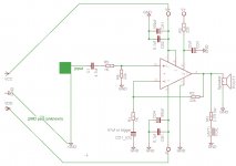
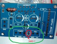
and double check there is a strange SMD sold pad between signal ground and power ground. I have no idea and info about it, is that pad has a purpose with it?
Some say is a "half a dozen" turns of coil and I will put together with a 10R/2w across it.
The RF2 does bring up question for me but i don't have a wave testing equipment(is that a scope?) at the moment.
Katieanddad, thanks for the end of tips
I find the schematic given by pcb seller looks so strange than others, so i just learnt and use eagle to re-draw schematic(1st in my life),

and double check there is a strange SMD sold pad between signal ground and power ground. I have no idea and info about it, is that pad has a purpose with it?

You are mixing up the terms, output inductor and output Zobel.
The output Zobel is a load the amplifier sees at high frequency and consists of a series combination of a resistor and capacitor. Typically 100nF and 10r
The Output inductor is a connection to the load that helps isolate the amplifier from the cabling going out across your room. It is usually a parallel combination of a resistor and air cored inductor: typically 2r and 1uH
The combined output inductor and the output Zobel were invented by Neville Thiele and often referred to as the output Thiele Network.
...... to the speaker ground return point....
Do not mean to interfere with the discussion, but my
question may be of some help for some people (including me). I knew the speaker ground return point should be
directly at the ground pin of the main PS capacitor....Is
this correct? Or should it be the ground pin of one of the
capacitors close to the amp IC?
Regards
Roushon.
It should be where the high speaker currents will not be able to interfere with any other ground returns. A big problem is when two channels are connected up to the same PSU and channel interaction occurs... this explains it all,
http://www.diyaudio.com/forums/soli...-lin-topology-nfb-tappings-2.html#post1624677
http://www.diyaudio.com/forums/soli...-lin-topology-nfb-tappings-2.html#post1624677
- Status
- This old topic is closed. If you want to reopen this topic, contact a moderator using the "Report Post" button.
- Home
- Amplifiers
- Chip Amps
- lm3886, advice before soldering
