Hi
I have a hum with my new LME 48930 amp. It is a 2 x 100 W (8ohms), with two pairs of 2SK1058/2SJ 102 mosfets. There is a single power supply +/50 V, ClC one, with 2 larges 22 mH capacitors, and 1,8mh self on each rail.
I don't understand why I have this hum, with the IN+ connected to ground.
Here's a capture of th e mesure with cold amp (5mv/2ms)

and the same (each chanel) 15 mn later (hot amp)

I try lots of thing: add big electrolytics caps, change value of bias cap, change the bias courant (130 mA on each mosfet), and no effect.
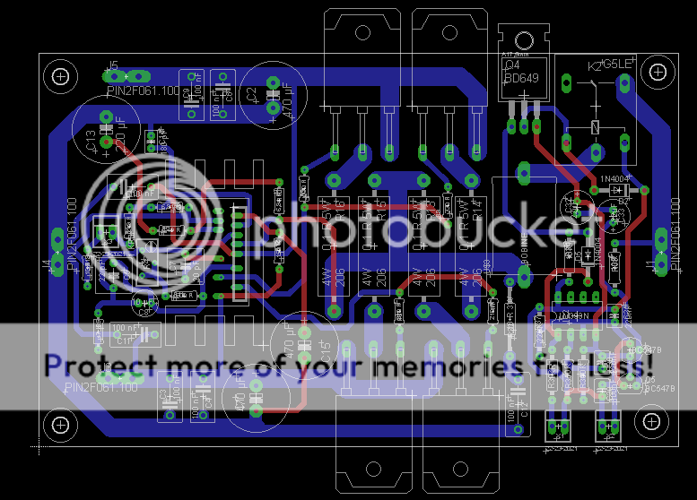
Here's the schema and the PCB. Can you help me?
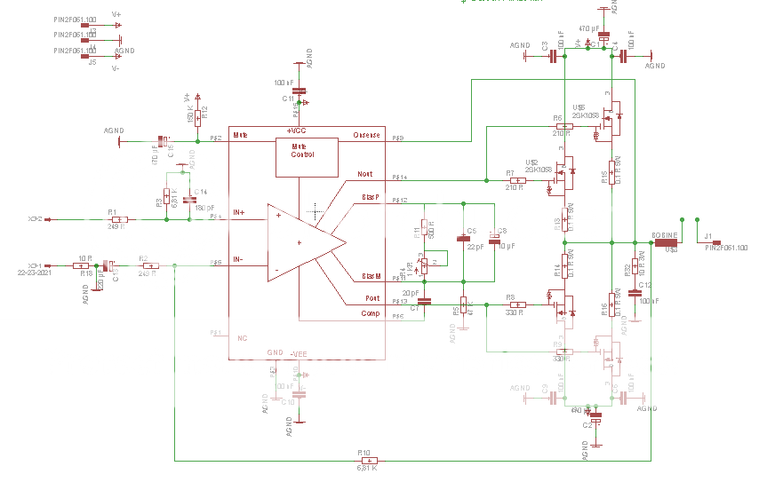
(there is a offset control)
Thanks!
Georges (sorry for my bad English)
I have a hum with my new LME 48930 amp. It is a 2 x 100 W (8ohms), with two pairs of 2SK1058/2SJ 102 mosfets. There is a single power supply +/50 V, ClC one, with 2 larges 22 mH capacitors, and 1,8mh self on each rail.
I don't understand why I have this hum, with the IN+ connected to ground.
Here's a capture of th e mesure with cold amp (5mv/2ms)

and the same (each chanel) 15 mn later (hot amp)

I try lots of thing: add big electrolytics caps, change value of bias cap, change the bias courant (130 mA on each mosfet), and no effect.
Here's the schema and the PCB. Can you help me?

(there is a offset control)

Thanks!
Georges (sorry for my bad English)
You could be seeing the cap charging currents imposed on a non-zero ground impedance. To see if this is so, please show the wiring of the main 22mF rail caps and how these connect to your PCB?
The only thing I can see potentially wrong in your grounding on the PCB is that you're using a noisy AGND to feed the mute pin - you could try moving this to a quiet ground (from the star). Oh and C14 also should go to the star, not to a noisy AGND. And R5 needs its own quiet ground, since the one it currently has is polluted by the noise current through C11.
The only thing I can see potentially wrong in your grounding on the PCB is that you're using a noisy AGND to feed the mute pin - you could try moving this to a quiet ground (from the star). Oh and C14 also should go to the star, not to a noisy AGND. And R5 needs its own quiet ground, since the one it currently has is polluted by the noise current through C11.
Last edited:
This is very likely.You could be seeing the cap charging currents imposed on a non-zero ground impedance. .
Bad Grounding and particularly sharing a charging circuit with an audio circuit trace or wire.
Thank you for your answer
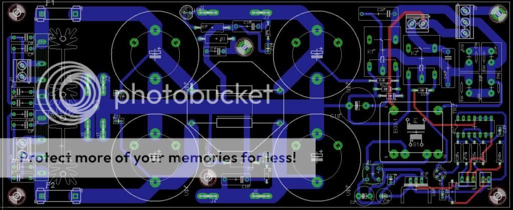
There is the schema, the PCB and two photos of the power supply with the amplifiers:
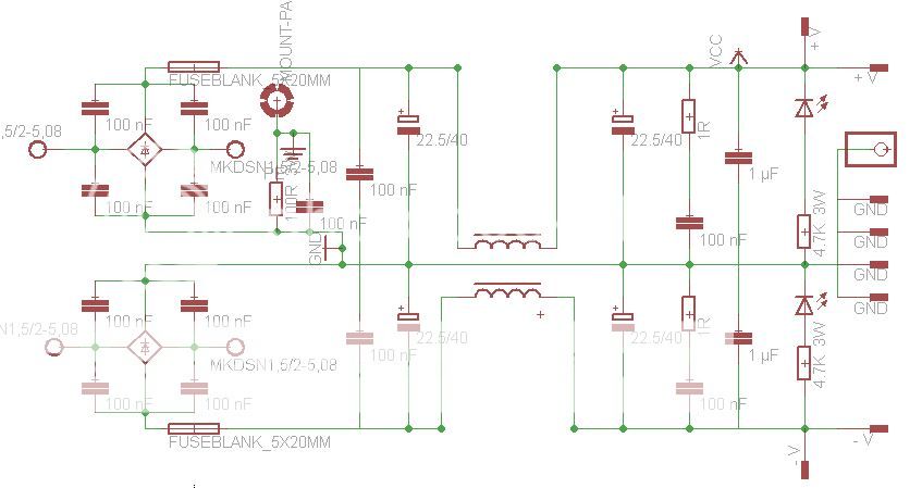
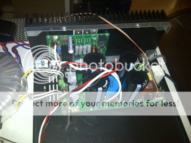

There is an flip flop and a soft start on the power supply you can't see on the schema.
The star ground is the five pins near the two bridges rectifier: two pins for amplifier's ground,, two for the HP's an one for the in signal.
The AGND is connected to the earth by a 100 R/100 nF.
For the mute, I try to change with a 5,1 V zener diode and the good value resistor to have 160 µA: no effect. I try an another power supply: it's worse!
May be a problem with the inductor just above the ground wire on PCB?
Georges
There is the schema, the PCB and two photos of the power supply with the amplifiers:


There is an flip flop and a soft start on the power supply you can't see on the schema.
The star ground is the five pins near the two bridges rectifier: two pins for amplifier's ground,, two for the HP's an one for the in signal.
The AGND is connected to the earth by a 100 R/100 nF.
For the mute, I try to change with a 5,1 V zener diode and the good value resistor to have 160 µA: no effect. I try an another power supply: it's worse!
May be a problem with the inductor just above the ground wire on PCB?
Georges
Last edited:
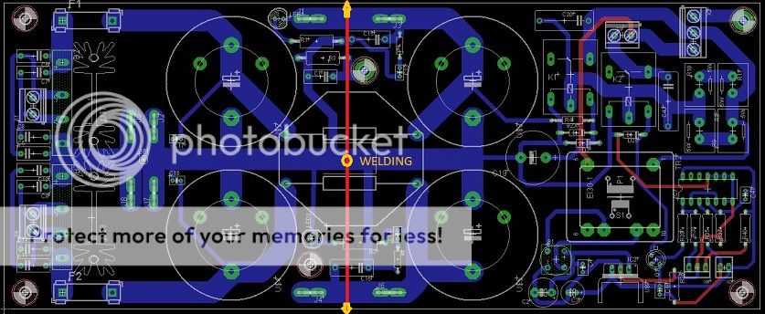
Thanks for providing the PCB layout for your PSU. Its clear from this that your 'star ground' isn't one in reality - that's because you have very large capacitor charging currents flowing through it (left to right) and so the tastons to the left will be at a different potential to those to the right.
A star ground really does mean a literal star - all connections to it must meet at an infinitesmally-sized point so that there are no ground impedances in common.
A star ground really does mean a literal star - all connections to it must meet at an infinitesmally-sized point so that there are no ground impedances in common.
This PSU come from TI Application note AN-1849.
I try something like that to connect the amplifiers ground (with a weding wire): thers's no effect . May be I don't understand something with the "real star ground"
Do you think I have to remove the self (just above the signal ground?)
Thank you!
I try something like that to connect the amplifiers ground (with a weding wire): thers's no effect . May be I don't understand something with the "real star ground"
Do you think I have to remove the self (just above the signal ground?)

Thank you!
The amplifier open loop gain is 120 dB (1,000,000) minimum. Any signal on the traces connected to pin 5 (- input) will be amplified 1,000,000 times. The long trace on pin 5 is an antenna. Both gain resistors should be connected to pin 5 with the shortest possible trace. This could be accomplished with a trace length of 0.25” or less.
Both gain resistors should be connected to - input with the shortest possible trace. This is also the case with discrete amps. Parallel traces next to or under the - input trace will capacitive couple unwanted noise or signals. You can verify the sensitivity of the - input by touching it with a test lead or your finger.
Last edited:
Fiscal,
The common mode choke (the inductor) is one of the main causes of your problems.
It is very strongly coupling the +ve rail current to the -ve rail and vice-verse - remember that in class AB the rail currents are more or less equal but opposite. Short it out and you will see improvement.
If you add inductors to the DC rails they must not couple.
Call me simple, but have you tried a bench top power supply instead of yours on this circuit and if so have you seen the same noise problem? This will focus your efforts. Hopefully you have a 50V power supply. Will the circuit work at +/- 30V? (Should be obtainable with any benchtop dual power supply.) Looks like that power supply is expecting exact sinusoidal waveforms on the + and - side. Asymmetry on the AC will cause one phase to influence the other via the inductor.
Lots of interesting things in your reponses: thanks!
I suppose my PSU is not the best I never made! I can't try an another one, because I don't have some. But I think to change it:
One by chanel, with a real star ground, with less components, without inductor, etc.
I will test the sensitivity of the -input.
I need a few days to think about this, and i'll come back
Thanks to everyone !
With the Scope AC coupled, what is on the +V and -V supply at the amp with the scope probe grounded at the amp? Can you power the amp without the line ground connected, just the scope line ground connected. To be safe make all the connection, then plug in the amp and don't touch anything with the amp line ground disconnected. Look at the amp output, +V and -V with and without the amp line ground connected. All testing with the input grounded at the input connector with a short jumper on the board.
Do the same tests with the amp unplugged, and 0V on both power supply caps.
Do the same tests with the amp unplugged, and 0V on both power supply caps.
Last edited:
Hi Fiscal, i came into this discussion rather late and sifting through the responses left me a little confused, i have assumed that the amplifier with only the speakers connected and no input connected you found the amplifier hums, if so that rules out any scope connexions, since the boards are standard and this arrangement has not had problems before by other users, in this case other things must be considered, hence the hum loop idea, so that for instance if you have the RCA sockets connected to the chassis and other earthing points also connected to the chassis then a hum loop will be in evidence, if all of these sockets etc are isolated and hum still persists then ensure that you have set the gain correctly on the driver chip if you have inadvertantly used a wrong value resistor and boosted the gain by a significant amount hum then might become an issue from the transformer field, by stray pick-up, just carefully go over the resistor values and preferably by measuring them, have had errors before from wrong colour coding, and make sure amplifier is isolated from chassis, also final check make sure all your electrolytics are inserted right way round on the silk screening..
Good- luck Humble
Good- luck Humble
- Status
- This old topic is closed. If you want to reopen this topic, contact a moderator using the "Report Post" button.
- Home
- Amplifiers
- Chip Amps
- Need help with my LME 48930 amp