Hi!
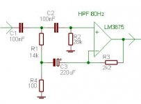
I've built me (for my ghetto blaster project) a high-pass GC, using a circuit from the nationals on-line filter calculator, like this:
With the following values:
R1 3200 K
R2 240 K
R3 2.2 K
R4 0.1 K
C1 2.2 nF
C2 2.2 nF
It should give a a xo-frequency of about 75 - 80 Hz with a Q of 0.6
Supply voltage is +- 35 V (25 - 0 - 25 toroid), with only GC-like 2 * 1000 uF at the pins of the IC, which is an OPA458.
When I turn on the amp, with no signal and no load connected, nothing happens (OK), supply voltages are OK, but at the output pin I have nearly the full positive output rail!
Has anyone some suggestions? This is the first time I am trying to use those filters... And I have to be finished until friday evening, since I want to use the blaster in my skiing holidays...
Thanks,
Arndt
I've built me (for my ghetto blaster project) a high-pass GC, using a circuit from the nationals on-line filter calculator, like this:
An externally hosted image should be here but it was not working when we last tested it.
With the following values:
R1 3200 K
R2 240 K
R3 2.2 K
R4 0.1 K
C1 2.2 nF
C2 2.2 nF
It should give a a xo-frequency of about 75 - 80 Hz with a Q of 0.6
Supply voltage is +- 35 V (25 - 0 - 25 toroid), with only GC-like 2 * 1000 uF at the pins of the IC, which is an OPA458.
When I turn on the amp, with no signal and no load connected, nothing happens (OK), supply voltages are OK, but at the output pin I have nearly the full positive output rail!
Has anyone some suggestions? This is the first time I am trying to use those filters... And I have to be finished until friday evening, since I want to use the blaster in my skiing holidays...
Thanks,
Arndt
Hi!
If the circuit is right, the wiring should be, as well. Checked both channels more than twice, both channels carry DC offset of approx. 34 V...
I will try my low pass (using OPA 541) next...
Bye,
Arndt
millwood said:could it be tha the wiring is faulty?
If the circuit is right, the wiring should be, as well. Checked both channels more than twice, both channels carry DC offset of approx. 34 V...
I will try my low pass (using OPA 541) next...
Bye,
Arndt
Hi!
Yeah, I meant the OPA 548...
Actually I found a mistake by back-engineering (drawing a diagramm by the connections I made)...
The feedback resistor (R3) is not from output to negative input , but to positive input...
On all of my four ICs...
Can not change it right now, maybe later...
Thanks anyway,
Arndt
Matttcattt said:i asume you mean OPA548 not OPA458.
are you sure you have the inputs the correct way round? i switched them on my amp (OPA548, then OPA541) and i got rail voltage at the output.
i mean inverting and non-inverting inputs on the chip, by the way.
Yeah, I meant the OPA 548...
Actually I found a mistake by back-engineering (drawing a diagramm by the connections I made)...
The feedback resistor (R3) is not from output to negative input , but to positive input...
On all of my four ICs...
Can not change it right now, maybe later...
Thanks anyway,
Arndt
")
Hi!
Is it somehow possible to lower the DC offset? Problem is, whenever I raise the resistance from negative input to ground, the gain decreases...
Is there a way to avoid this change in gain and filter characteristics, but still dropping DC offset (I want to achieve at least <100 mV)?
Thanks,
Arndt
Is it somehow possible to lower the DC offset? Problem is, whenever I raise the resistance from negative input to ground, the gain decreases...
Is there a way to avoid this change in gain and filter characteristics, but still dropping DC offset (I want to achieve at least <100 mV)?
Thanks,
Arndt
Cradle22 said:Hi!
I've built me (for my ghetto blaster project) a high-pass GC, using a circuit from the nationals on-line filter calculator, like this:
With the following values:
R1 3200 K
R2 240 K
R3 2.2 K
R4 0.1 K
C1 2.2 nF
C2 2.2 nF
It should give a a xo-frequency of about 75 - 80 Hz with a Q of 0.6
Hi,
You use IMHO wrong R and C combinations (too high impedance network). For first decade filters recomended caps value are 100nF to 470nF.
Also, increase feedback resistors ten times and use large elco in series with R4 for avoiding DC offset problems.
Regards
Re: Re: Problems with HP GC, urgent
Hi!
I have used small feedback resistor values because is was adviced to do so in this thread:
active XO GC
Can I use "normal" feedback values without risking instability?
Only two days unti this has to work...
Bye,
Arndt
Hi!
moamps said:
Hi,
You use IMHO wrong R and C combinations (too high impedance network). For first decade filters recomended caps value are 100nF to 470nF.
Also, increase feedback resistors ten times and use large elco in series with R4 for avoiding DC offset problems.
Regards
I have used small feedback resistor values because is was adviced to do so in this thread:
active XO GC
Can I use "normal" feedback values without risking instability?
Only two days unti this has to work...
Bye,
Arndt
Hi,Cradle22 said:Putting a 22uF polarized cap between R4 and ground reduced offset to 12 mV, but also introduced massive distortions!
f(-3) for 22uF/100ohm is ca 70Hz, what is too high. Try 220uF, maybe.
Regards
Cradle22 said:Is it somehow possible to lower the DC offset? Problem is, whenever I raise the resistance from negative input to ground, the gain decreases...
[/B]
The gain is determined by a *ratio* of the feedback resistor to the resistor from the inverting input to ground. So, if you want to increase the value of the inverting-ground resistor, you simply increase the feedback resistor by the same factor!
It seems to me, however, that you will want to reduce the values of those two resistors in order to reduce your DC offset.
Good luck!
Hi!
I know how to calculate the feedback resistors. And I would say that it is easier to reach lower DC offset by increasing the values, but still there was this statement of someone who said that the feedback resistors should be small in a sallen-key topology, which should lead to a better rolloff at the XO frequency.
Don't know if I have the time to do some more work on this today, and tomorrow I'm off for Saas Fee (which is what I've built this thing for in the first run)...
Bye,
Arndt
Nappylady said:
The gain is determined by a *ratio* of the feedback resistor to the resistor from the inverting input to ground. So, if you want to increase the value of the inverting-ground resistor, you simply increase the feedback resistor by the same factor!
It seems to me, however, that you will want to reduce the values of those two resistors in order to reduce your DC offset.
Good luck!
I know how to calculate the feedback resistors. And I would say that it is easier to reach lower DC offset by increasing the values, but still there was this statement of someone who said that the feedback resistors should be small in a sallen-key topology, which should lead to a better rolloff at the XO frequency.
Don't know if I have the time to do some more work on this today, and tomorrow I'm off for Saas Fee (which is what I've built this thing for in the first run)...
Bye,
Arndt
Hi!
Well, looking at the thomson application notes for the TDA2030A, where they implement something like I want to do, I realize that they also added polarized caps in series to the output, which is also a (not preferred) way to get rid of DC offset...
But since sound quality is not of highest priority on my wish list, I will also try that (it should still be better than the average boombox out there).
Bye,
Arndt
Hi!
I've built "your" circuit exactly as you described it, but without C3, and got -2.4 V DC offset...
I think I will leave this idea alone, get me some active XO boards from ESP, and use them...
No use for my upcoming holiday, but the next one is in February...
Thanks anyway,
Arndt
I've built "your" circuit exactly as you described it, but without C3, and got -2.4 V DC offset...
I think I will leave this idea alone, get me some active XO boards from ESP, and use them...
No use for my upcoming holiday, but the next one is in February...
Thanks anyway,
Arndt
- Status
- This old topic is closed. If you want to reopen this topic, contact a moderator using the "Report Post" button.
- Home
- Amplifiers
- Chip Amps
- Problems with HP GC, urgent