I connected the bulb in series with primary but it was when I was testing first time. Problems mentioned in my recent posts are when I connected the transformer directly into the power without the bub in series.Where have you connected the light bulb ?
Is it in series with primary,then I doubt you have erred in connecting the diodes as well.
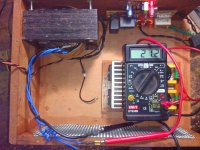
I am using a 35A bridge rectifier where diodes are inbuilt. When I measure the volts at +/- of this BR, it shows 48 (double of 24-0-24). But when I take reading at the end after 0.1uf, ground + positive side shows 72 and negative + positive shows 144.
This is the mystery that why such high volts?
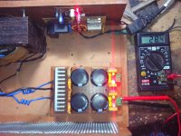
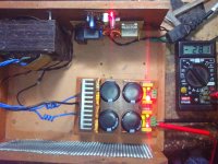
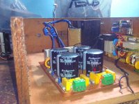
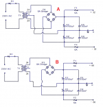
Hi jack it was nice to see you building the lm 3886 GCs. I am currently using it for my triamped floorstander project. Its a long way to go. Have not yet built the speakers but have tested with my old 2way bookshelf, the sound is awesome . I had built a robust power supply though myself and had designed the pcb layout. Sharing the pics here. Hope u get some idea. A single board is used to drive 2 lm 3886 working in bridge mode.
Specs: Xformer. Torroidal 2*25v dual secondary outputs 300va. To drive the low bass woofer. These will drive two individual bridged lm3886 configuration for both channels.
Xformer. Torroidal 2*25v 160va centre tap to drive mid woofer through 2 lm3886 boards.
Specs: Xformer. Torroidal 2*25v dual secondary outputs 300va. To drive the low bass woofer. These will drive two individual bridged lm3886 configuration for both channels.
Xformer. Torroidal 2*25v 160va centre tap to drive mid woofer through 2 lm3886 boards.
An externally hosted image should be here but it was not working when we last tested it.
Last edited:
Below are pic of my current project
It have a 21-0-21 8Amp transformer.
Now by formula 21 vAC should give ??? vDC
(21*1.414)-1.4 = 28.29 vDC
And you can see that after rectification I am getting same voltage.
So i think their might be some problem with your 24-0-24 transformer OR any thing else.
You have tested another PSU you purchased earlier, that too is giving high voltage..
Attachments
Last edited:
You have tested another PSU you purchased earlier, that too is giving high voltage..
That PSU even fried, lost most of the caps on that PSU.
I even went at a known electrical mechanic's shop to get verified the readings and found that readings were same like what I was getting. He also declared that the 28-0-28 is not working right and there maybe some issue with the 24-0-24.
Vendor said that the 24-0-24 he is giving to me is a multipurpose tranformer and it can also be used into the invertor. Inverters usully have high VA rating something like 650, 850va etc. If we consider it to be a usually 850VA rating then Amps turn out to be around 30 which is way above tolerance.
Will go to the vendor today and will get everything checked at his place before taking back these transformers. THis time I will tell him the VA, instead of +/-v, A requirements. I think 24-0-24 should be around 200va rated and 28-0-28 should also be similar. IS that correct?
BTW, should I get 20 or 22 volt transformer since 28V is maximum power required to drive 4ohm speakers and our PSU is turning the final volts into around 32 which maybe excessive for the LM3886?.
I saw the pictures but didn't find any heatsink in your project, aren't you using any heatsink? Or there is some other method you are using to keep the ICs cool?Hi jack it was nice to see you building the lm 3886 GCs. I am currently using it for my triamped floorstander project.
An externally hosted image should be here but it was not working when we last tested it.
Last edited:
That PSU even fried, lost most of the caps on that PSU.
Caps on that PSU were rated 50 volts and they are destroyed.. Definitely transformer is faulty.. giving much higher voltage..
How can it be determined?Or your center tap is connected the wrong way.
I told you he damn thing before you even sarted the damn thing!
There are 2 secondary coils, if you find them, mark them, connect first start to another end. boom there you have it, not that easy but its easy...
Make sure that the two single leads are out of phase with respect to each other.
Like you get measurement of 48V on both leads tha are not connected... and between the "center tap" you have 24b on both sides... BUT IF YOU DONT then you have 24V only between center and other 2... Yet, if you have 24-0-24 but no 48-48 Your amps will burn.
I saw the pictures but didn't find any heatsink in your project, aren't you using any heatsink? Or there is some other method you are using to keep the ICs cool?[/QUO
Jack> the picture you have seen is of the PSU only. The amp boards are seperate and mounted on a heat sink. With a dedicated dc fan. It is very essential to keep these ICs cool else you will not get the desired wattage you are looking for. As these ICs tend to lower the output power if there is a thermal issue.
Jack> the picture you have seen is of the PSU only. The amp boards are seperate and mounted on a heat sink. With a dedicated dc fan. It is very essential to keep these ICs cool else you will not get the desired wattage you are looking for. As these ICs tend to lower the output power if there is a thermal issue.
Thanks for the diagram, my transformer vendor also explained the same thing by saying that I can get 48v (66+ after rectification) power by skipping the '0' from transformer.
Now I am curious that why we use 24-0-24 transformer instead of a 12-0-12? We can get double power form the 12-0-12 by skipping the ground wire and can use ground form the rectifier.
Now I am curious that why we use 24-0-24 transformer instead of a 12-0-12? We can get double power form the 12-0-12 by skipping the ground wire and can use ground form the rectifier.
Yeah, I am trying to take extra precautions while playing with electricity thats why I don't repeat my tests again n again and if there is any confusion, I put it here first. Also reading as much as I can on all these stuffs.
------------
Anyways, been at the transformer guy's place and everything was fine at his place except one of the transformer's low volt rating which was actually 23-0-23 instead of 28-0-28. Fault was that the center tap wires were wrongly placed ad the transformer guy corrected them and it started running fine.
Both transformers were giving there rated readings and surprisingly my PSU was also giving desired readings. I didn't make any changes in the PSU, I connected it how I connected at my home but it was behaving weird at while I checked and started running fine at the transformer guy's place. Checked with both transformer and it was right.
I think some connection on the PSU might have loosen at some point of time and it may have again come into place when was carrying it. Will check all the connection and loose soldering and will test back the stuffs in the night.
So finally now I have two transformers:
23-0-23, 8A.
24-0-24, 5-10A. (There is also a provision to use it in 22-0-22v mode)
Planning to use the 23v with 5 X LM3886 and 24v with 200W Toshiba sub AMP. But problem is 18-0-18 tapping was left in the 23 one. Will see what can be done.
Last edited:
Planning to. Use the 23v with 5 X LM3886 and 24v with 200W Toshiba sub AMP. But problem is 18-0-18 tapping was left in the 23 one. Will see what can be done.
Jack > the toshiba modules on the sub amp Are they original have u checked that. Becoz toshiba is not manufacturing them now a days. Toshiba 2SA1943 / 2SC5200 are available in duplicate form and will get damaged if current more than 2 amps flow through it. Pls be double sure when powering them and post your experience with their o/p s. By the way what driver you are using for the subwoofer.
I bought the AMP board from here : Wintek - 200W Mono (Toshiba 2SA1943 / 2SC5200)now a days. Toshiba 2SA1943 / 2SC5200 are available in duplicate form and will get damaged if current more than 2 amps flow through it. Pls be double sure when powering them and post your experience with their o/p s. By the way what driver you are using for the subwoofer.
Can't say anything if they are genuine or not, hope they are genuine.
Earlier there was some unbranded 12" driver which I replaced with a 12" Peerless India 160W, 4ohm driver for the sub which also bought form the above website and I must say, this was what I I was looking for, nice deep rich bass, no annoying boom-boom like my previous driver.
I think Peerless drivers are good options in budget range for DIYers.
I bought the AMP board from here : Wintek - 200W Mono (Toshiba 2SA1943 / 2SC5200)
Can't say anything if they are genuine or not, hope they are genuine.
Earlier there was some unbranded 12" driver which I replaced with a 12" Peerless India 160W, 4ohm driver for the sub which also bought form the above website and I must say, this was what I I was looking for, nice deep rich bass, no annoying boom-boom like my previous driver.
I think Peerless drivers are good options in budget range for DIYers.
We both are on the same boat. I have plans to build the transmission line subwoofer.It will be done once I complete my subwoofer amplifier . I am currently designing a PCB and will be using the lateral mosfet for the sub. 2sk1058 and 2sj162. They are brilliant and can handle more power, the construction is very simple once you get hold of a genuine supplier
There is a. Manufacturer and supplier known to me who had provided me torroidal transformer online at very competitive rates and they can custom build trafos according to your need. And they are just superb. Will send u link if u r interested.
Just to suggest if you can build your own pcb the cost of the project can be brought to minimum for the electronics and you can spend rest amount on good speakers like jbl or kicker for the subwoofer.one of my friend have built one and they easily go as low as 18 hz. In a transmission line design. And better than any high end subwoffer I have heard before.
Please send me the link, will be handy in future.There is a. Manufacturer and supplier known to me who had provided me torroidal transformer online at very competitive rates and they can custom build trafos according to your need. And they are just superb. Will send u link if u r interested.
- Status
- This old topic is closed. If you want to reopen this topic, contact a moderator using the "Report Post" button.
- Home
- Amplifiers
- Chip Amps
- Help Needed on DIY LM3886 based 5.1 Channel AMP for PC Home Theater