But I thought the PSU and the Load did form a high pass filter.Haven't ever asked why............... the power supply caps combined with the load do not form a high-pass filter ?
It is the job of the amp designer to ensure this high pass filter is set low enough that it does not compromise the performance of the amplifier/speaker.
What the hell people, power supply has nothing to do with output filtering.
If supply rails are thin and long that high current can not pass thru then yes, the bass is super shi*.
But one and only good thing about output capacitor is... DC protection and thats all.
As far as i know the output capacitor should be at least biopolar to receive nice and smooth sq wave output.. if needed as "good" measurement.
The same thing is with input capacitor but normally its alot smaller and if theres electrolytic cheap piece of crap in use, then the amp sounds horrible.
But you know what? I might be wrong.
Minion had a point about the good square wave response. A square wave is DC, for a short time. With a very low repetition rate, it could be DC for as long as you wanted. But staying at rep rates corresponding to audio frequencies, say, not below 20 Hz worst case, you can derive the reservoir and output capacitance values that would be required to accurately reproduce the square wave. Luckily for the reservoir caps, there is a charging pulse every so often. So they only need to be able to provide current for that long (ideally). But their value also depends on how much you want to allow the power rail voltage to sag, before the next charging pulse.
Keep in mind, too, that the output signal IS THE CURRENT from the reservoir caps. (Check out the plot image attached to the post at http://www.diyaudio.com/forums/power-supplies/240955-resevoir-capacitors-chip-amps.html#post3599692 .)
We usually look at the output cap value in the frequency domain. Maybe also thinking about it in the time domain would be helpful. For the low-frequency square wave example, wouldn't the output cap need to be able to accept all of the current that the reservoir caps provided, without getting "too full" such that the voltage across it mis-behaved? And it doesn't get relief from the charging pulse period. It has to wait until the signal polarity switches, before it can unload charge from whatever extreme it was made to go to.
This is the first time I have thought of the output cap this way (and I'm in a bit of a rush) so I might have said something silly. But it might be food for further thought.
Last edited:
Oh thank you so much Mikhus.")
I have two 12 Volt SMPS. But unfortunately one is showing 12.78V and another 12.95. So Not perfectly symmetrical. Will that distort the sound or cause DC offset at the output?
Or do you suggest me to obtain a 24V SMPS and then split it with a bridge rectifier and electrolytic caps (if that is possible at all ) ?
Kindly guide me to hack the 12v one to a dual 12v.
You can not split a single 24V to +/-12 with just a bridge rectifier. There are a few ways to split the supply but it would mean a lot of wasted power similar to that drawn by a Class A amplifier.
'
<< For opamps ive used resistors and zeners but never heard of bridge rectifier...>>
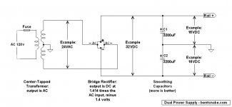
A bridge rectifier (search for it by that name) is just 4 diodes in a single small package, less than the size of a dime. It has two AC-in legs, and a plus and minus leg each for DC-out. Very convenient for bolting together power supplies.
Note that a bridge rectifier drops about 1.4 volt across itself, so allow for that in the expected output voltage. In fact, see below.
.
<< For opamps ive used resistors and zeners but never heard of bridge rectifier...>>
A bridge rectifier (search for it by that name) is just 4 diodes in a single small package, less than the size of a dime. It has two AC-in legs, and a plus and minus leg each for DC-out. Very convenient for bolting together power supplies.
Note that a bridge rectifier drops about 1.4 volt across itself, so allow for that in the expected output voltage. In fact, see below.
.
Last edited:
.
It doesn't answer the question, but I just want to make an announcement: Everybody quit being afraid of dual power supplies.
Power supplies are not complicated. Yes, you can make them that way, and the people who do love to talk about it. But there's only one way to rectify AC into DC, and it's been that way since Tesla joined with Westinghouse to make AC (not Edison's DC) the power standard of the world.
Hoping to prove my point, here's a circuit diagram for a power supply. This circuit is intended to be explanatory, it's not a construction project, but you could build it as it is and it would work as intended.
Dual power supplies give double the "headroom," and they make the circuits they power simpler, meaning fewer parts, less expense, fewer chances for error, life is better in general. Unless you like making things complicated just for fun, KISS.
.
Attachments
Last edited:
The output swings between the rails. Usually clips before actually reaching the rail voltage.
It does not matter whether there is a "middle" reference of a dual polarity supply, or a single supply with just +ve and -ve.
A 20W amplifier could output maximum power from a +-20Vdc dual polarity supply and just as capably produce the same maximum power from a 0V, -40Vdc supply, or a 0, +40Vdc supply.
hmm..
not strongly related, but what would be better,
rail-to-rail reservoir, or rail to ground ?
Large rail to rail capacitors plus smaller rail to ground capacitors would be great for a bridged amp, not so good for an amp with its load-return connected to power-ground.
This may be stupid but put a load on a capacitor on the output of some signal generator, be it an amp or what not. Listen to it... does it change the sound? The most detrimental aspect would be a loss of bass with low impedances. That can be equally made up for with high capacitance. The end result is the same to the ear IMHO.
- Status
- This old topic is closed. If you want to reopen this topic, contact a moderator using the "Report Post" button.
- Home
- Amplifiers
- Chip Amps
- Split Supply Vs Single Supply - Is there difference in sound quality?