Joe Rasmussen "Trans-Amp" - 40 Watt Transconductance "Current Amplifier"
.
PLEASE BUILD THIS WITH DUE CAUTION!
[Click on it to enlarge]
There are good reasons why there are no "Current Amplifiers" on the market today, with exception of the Nelson Pass F1 and F1J amplifiers. This DIY project is about building a low cost 40 Watt Transconductance Amplifier using National Semiconductor's LM3875T.
WHY BUILD ONE?
Before going ahead: READ THIS BY NELSON PASS: Current Source Amplifiers / Full Range Drivers
Conventional amplifiers are of course "Voltage" types, where the amplifier outputs Voltage similarly to what we see on an oscilloscope with X-Y axis' representing Voltage (vertically) versus Time (laterally). The current is dependant on the load.
With a "Current" type amplifier, this is far less intuitive to understand, but basically it is the opposite, here the voltage is dependent on the load.
It becomes then clear that the Voltage Amplifier needs to have a low output impedance, so that the amplifier can control the Volts without any sagging. Effectively, the Voltage is 'regulated.'
What is not so clear is that a Current Output Amplifier needs to have a VERY HIGH OUTPUT IMPEDANCE!
So a Voltage Amplifier is defined by its Low Impedance.
A Current Amplifier is defined by its High Impedance.
The notion that there is any such thing as "Damping Factor" - with a Current Amplifier - forget it!
Indeed Damping Factor is largely a myth, what really happens, as Richard Small told me way back in 1975 (he is the S in T-S), that any series impedance/resistance with the Voice Coil erodes Qes and if high enough, destroys the speakers Bass Alignment - so that the Electrical Damping Qes within the speaker is non-existent.
If the DCR of the Voice Coil is 6 Ohm and Qes = 0.5, then an additional series of 6 Ohm will double the Qes = 1.0... and so on. Your Bass Alignment no longer works.
SO THIS AMPLIFIER CAN DAMAGE THE WRONG SPEAKERS!
For the technically minded: The Qes and Qms of the driver that determines its part of the bass alignment, these two are in parallel. If the Qes is eroded completely away, then take note of the Qms as the real Q of the alignment. That way we can plot what that particular alignment does in software. Enter T-S Parameters and Box details, but modify Qes to 1000, enter correct Qms value, then it will plot the actual 2Pi response when driven by a current amplifier.
Also, the Crossover (High Pass) to the Tweeter could also damage it in a very short time.
Yes, the use of Current Output Amplifiers are suitable for Full Range Drivers and also speaker systems that are designed to work with current.
Such as the latest Elsinore Mk6 Loudspeaker Project.
Cheers, Joe R.
.
.
PLEASE BUILD THIS WITH DUE CAUTION!
[Click on it to enlarge]
There are good reasons why there are no "Current Amplifiers" on the market today, with exception of the Nelson Pass F1 and F1J amplifiers. This DIY project is about building a low cost 40 Watt Transconductance Amplifier using National Semiconductor's LM3875T.
WHY BUILD ONE?
Before going ahead: READ THIS BY NELSON PASS: Current Source Amplifiers / Full Range Drivers
Conventional amplifiers are of course "Voltage" types, where the amplifier outputs Voltage similarly to what we see on an oscilloscope with X-Y axis' representing Voltage (vertically) versus Time (laterally). The current is dependant on the load.
With a "Current" type amplifier, this is far less intuitive to understand, but basically it is the opposite, here the voltage is dependent on the load.
It becomes then clear that the Voltage Amplifier needs to have a low output impedance, so that the amplifier can control the Volts without any sagging. Effectively, the Voltage is 'regulated.'
What is not so clear is that a Current Output Amplifier needs to have a VERY HIGH OUTPUT IMPEDANCE!
So a Voltage Amplifier is defined by its Low Impedance.
A Current Amplifier is defined by its High Impedance.
The notion that there is any such thing as "Damping Factor" - with a Current Amplifier - forget it!
Indeed Damping Factor is largely a myth, what really happens, as Richard Small told me way back in 1975 (he is the S in T-S), that any series impedance/resistance with the Voice Coil erodes Qes and if high enough, destroys the speakers Bass Alignment - so that the Electrical Damping Qes within the speaker is non-existent.
If the DCR of the Voice Coil is 6 Ohm and Qes = 0.5, then an additional series of 6 Ohm will double the Qes = 1.0... and so on. Your Bass Alignment no longer works.
SO THIS AMPLIFIER CAN DAMAGE THE WRONG SPEAKERS!
For the technically minded: The Qes and Qms of the driver that determines its part of the bass alignment, these two are in parallel. If the Qes is eroded completely away, then take note of the Qms as the real Q of the alignment. That way we can plot what that particular alignment does in software. Enter T-S Parameters and Box details, but modify Qes to 1000, enter correct Qms value, then it will plot the actual 2Pi response when driven by a current amplifier.
Also, the Crossover (High Pass) to the Tweeter could also damage it in a very short time.
Yes, the use of Current Output Amplifiers are suitable for Full Range Drivers and also speaker systems that are designed to work with current.
Such as the latest Elsinore Mk6 Loudspeaker Project.
Cheers, Joe R.
.
Last edited:

.
A FEW NOTES:
What is a Transconductance Amplifier?
Basically, this is an amplifier that has a Voltage input and outputs an equivalent defined Current output.
In this case, this amplifier is designed for 100mV signal input, to produce 0.25 Amp - or 250mA output. Hence 200mV input will produce 500mW input and 400mV input produces 1 Amp, and so on.
Voltage in and a specific Current out.
Look at the column to the right of the Schematic, called STRUCTURE.
If 100mV input and we have a 4 Ohm Load, then 250mA through that 4 Ohm Load should gives us 1V exact. We come very close indeed at 1.031V measured.
I an 8 Ohm Load is used, then we should see 2V and we get 2.033V measured.
We can now see that this is indeed behaving as a transconductance device, and the small error means we can calculate the Output Impedance as near 270 Ohm.
Note too, that the Voltage Gain is dependant on the Load. Hence the Gain is 10 (20dB) with 4 Ohm and 20 (26dB) with 8 Ohm, and so on.
PLEASE NOTE THAT THE SCHEMATIC IS ALSO A WIRING DIAGRAM.
Also:
USE ENTIRELY DUAL-MONO CONSTRUCTION.
So you will need TWO Power Transformers, min 160VA.
You could also use a single Power Transformer, but will double the number of Secondaries. If you don't get the wiring right, expect a fair amount of hum. It seems that the LM3875 is internally signal referenced to the Negative Rail +35V. So it is important to get it right.
When constructed, you will need to null the output. Use a 10R Resistor, then to fine-tune I would use a 100R value. Keep in mind that DC on the output also changes with Load. Ideally, with no Load connected, the 470R should see no DC.
Note the Resistor 0R33 - I used three 1 Ohm Resistors in parallel. These must be low inductance and the 6.5W rating is minimum.
This 0.33R is the "Current Sense" Resistor. The LM3875 input voltage on Pin 7 "+" input, also appears at Pin 8 "-" input. Don the maths and with 100mV on both pins, the current through our "Current Sense" Resistor will be 303mA. This does not seem to match our target of 250mA? But it does match after the input loss of the Bandpass Filter on the input of the RCA, so that 100mV on the RCA input will give us close to 250mA output.
About that Bandpass Filter, it is worth experimenting with the sonic influence of 1n5, so tweak this, reduce it to brighten the balance or find the sweet spot you like, and increase it as well. So tweak away, but don't entirely remove it. There are slew-rate reasons to include it as it inter-acts with the internal "Comp-Cap" of the LM3875 and helps define reduced feedback above 100MHz.
Next... some interesting measurements...
Maybe refrain from adding comment until they are posted, and I am finished.
Cheers, Joe R.
.
Last edited:
Good to see you finally get this going Joe.
We have had a somewhat similar transimpedance amplifier kicking around for the last few years (ours has variable output impedance so that you can dial in the output impedance that works best with your speakers).
Buried in what Joe said, and that is important to remember, is that the system response is the FR of the speaker (measured being driven with a voltage amp) convolved with the speaker's impedance.
Since a speaker is controlled by current not voltage there are some significant gains in distortion reduction to be had with a current amp -- with a voltage amp the speakers impedance acts as an imperfect V/I converter.
A good reference http://www.diyaudio.com/forums/vend...ook-current-drive-loudspeakers-published.html. His book is recommended.
dave
.
1 WATT DISTORTION MEASUREMENTS:
The "First Watt" is always the most important. All below measurements were made into an 8 Ohm Dummy Load.
1 Watt THD 0.023% & THD+N 0.051%
Note that Odd Orders are well suppressed. Small amount of 1/3rd and 1/5th. All the others are Even-Orders and of less concern, even if elevated relative to Odd-Orders. Higher power measurements shows an interesting trend, the Odd-Orders are on their own plateau than the Even-Oders on a higher plateau. So please continue...
1 Watt IMD 0.026%
The clusters form around Even-Order frequencies. Quite pleased.
Next, higher 10 Watt measurement.
Cheers, Joe R.
.
Last edited by a moderator:
.
10 WATT DISTORTION MEASUREMENTS:
10 Watt THD 0.023% & THD+N 0.028%
Here we see that interesting trend again. All Odd-Orders are suppressed relatively to the Even-Orders immediately above and below - on a lower plateau.
10 Watt IMD 0.024%
Quite pleased.
Cheers, Joe R.
10 WATT DISTORTION MEASUREMENTS:
10 Watt THD 0.023% & THD+N 0.028%
Here we see that interesting trend again. All Odd-Orders are suppressed relatively to the Even-Orders immediately above and below - on a lower plateau.
10 Watt IMD 0.024%
Quite pleased.
Cheers, Joe R.
Last edited by a moderator:
.
And interesting trend when looking at 10 Watt THD:
I would ignore that 16KHz peak, I seem to get this quite often when using 96K sampling frequency with other DUTs (devices under testing). So it is an aberration of some kind.
DO YOU SEE THE TREND?
The Black lines join Even-Order Harmonic Distortions and the Blue the Even-Orders. Note they are on different levels or plateaus?
I see a similar charactersitics in the 10 Watt and 20 Watt IMD measurements, the IMD clusters are visible for the Evens, but noticeable suppressed for the Odds.
This may well seem a characteristic for transconductance amplifiers.
I can say that the amplifier is very nice to listen to, IF you have compatible loudspeakers. Not your ordinary Chip Amp.
Cheers, Joe R.
PS: I also have 40 Watt THD measurement, showing that it clips well above 40 Watt. Also have IMD measurements up to 20 Watt (with current setup limited to 20W IMD). May post these later.
.
Last edited by a moderator:
Good to see you finally get this going Joe.
Thanks, Dave. The last two months has been as busy as I have ever experienced, rather tired at the moment.
I have that book and have had a few exchanges with him. The point is really this, for those who are reading this and not in the know, all 'motors' are current devices and it is current that makes them move. So there are significant reduction in phase noise (increased clarity), that comes from current driving.
But what do you think of those measurements, this is not the way a regular chip amp would measure, that's for sure. So into a non-reactive 8 Ohm Load, they look rather good and not exactly the norm.
I wish I had a straight chip amp here that I could measure and compare.
Off to the Post Office...
Cheers, Joe
PS: The dial-in output impedance is a neat idea - not so easily implemented with this design, as I see it.
BUT... Take a 15 Ohm large Wattage Resistor and put in parallel with the speaker (so that the amp also sees it), and that 270R output Z will come down - vary that resistor, but don't drop below, say 10R, with 4 Ohm speakers. So 10R to 100R will do a similar job - albeit drawing a bit of power/loss.
.
Last edited:
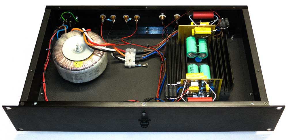
This is the one I built. I uses only a single 300VA transformer, but I don't recommend it. It was very tricky indeed. Best to go with separate transformers, or be prepared to sort out some issues.
Note that the Heatsink needs to be a good size.
Note the use of Jantzen Superior Red input coupling capacitor. I highly recommend it - as this needs to be of high quality.
Note that the Heatsink needs to be a good size.
Note the use of Jantzen Superior Red input coupling capacitor. I highly recommend it - as this needs to be of high quality.
Last edited by a moderator:
nice project, you always come with a fresh design. how does it sound compare to a standard LM3875?
Regards
Regards
Is the DC Trim pot shown correctly on the schematic? Is there any reason that other power amp ICs won't work or not be suitable for this design?
nice project, you always come with a fresh design. how does it sound compare to a standard LM3875?
Regards
Better !!!!
To me, it sounds like a completely different amplifier.
Cheers, Joe
Is the DC Trim pot shown correctly on the schematic?
It must be, since it actually works! 😀
Is there any reason that other power amp ICs won't work or not be suitable for this design?
Would I use this exact circuit? No, as the bandpass filter on the input and the DC trimming may be completely different - so while it is possible to use others, I cannot foresee what needs to be sorted.
Cheers, Joe
This seems a very interesting project to try. Thanks Joe for sharing. I already have on hand two 400VA transformers with 2 x 24V output. Except for giving away a couple of watts at the output can I use them to give a try to your design with my Elsinore speakers?
Last edited:
I already have on hand two 400VA transformers with 2 x 24V output... can I use them to give a try to your design with my Elsinore speakers?
Sounds like a good idea to me.
Just a quick one, are you able to do a basic impedance plot on your Elsinores? It should not be required, but a good idea to do before current driving them - it is not a hard thing to do.
Cheers, Joe
.
Sounds like a good idea to me.
Just a quick one, are you able to do a basic impedance plot on your Elsinores? It should not be required, but a good idea to do before current driving them - it is not a hard thing to do.
Cheers, Joe
.
What is a basic impedance plot, Joe?
I remember an Analog Devices EE who had a transconductance amp design in one of their Data application books, back 20 or so years ago. Rated for 50w, you were allowed to build two amplifiers without consent for personal use, more contact AD. It was a very high end design where the designer didn't spare quality. Even when a typical Zener diode would have been used was made discretely (they are quite noisy). Outputs were IGBT's. Specs were very impressive. Listed parts included the PCB layout et al.
Joe, wondered why you left off the output filter that prevents ringing with capacitive loads. Unnecessary unless using this type of load I would expect, contact you for mod if using this type of setup? Or just slap on a 0.7uH in parallel with a 10Ω in series with the output as in the data sheet pdf?
Joe, wondered why you left off the output filter that prevents ringing with capacitive loads. Unnecessary unless using this type of load I would expect, contact you for mod if using this type of setup? Or just slap on a 0.7uH in parallel with a 10Ω in series with the output as in the data sheet pdf?
Voltage gain = Speaker impedance / 0.33
Because speaker impedance vary with frequency then voltage gain vary with frequency too.
I saw such as design from Elektor magazine many years ago. But this design never success commercially.
Maybe people don't like hear from speaker that drive by current.
Because speaker impedance vary with frequency then voltage gain vary with frequency too.
I saw such as design from Elektor magazine many years ago. But this design never success commercially.
Maybe people don't like hear from speaker that drive by current.
Ok, A little research told me what is an impedance plot. Sorry for my not perfect understanding of english language. But I would like to know how do you measure it.
Interesting. How stable is this circuit, since the LM3875 is pretty prone to oscillation. The floating input could be a bit tricky. Would like to try such amp for my open baffle mids (Phy-Hp H21LB15) but the floating input might be a little concern in a three-way active system where proper earthing is a bit of a hassle. Have had an with floating inputs before and that simply didn't work, lot's of disturbance. The amp on it's own was o.k. but in a complex active system it was the cause of earthing problems.
Could I use an input transformer to tie the primary to PSU ground and leave the secondary floating ?
I have been thinking of building a Pass F2 before but the enormous power use of these monsters held me back. My system is almost always on, from 4 to 16 hours a day, every second I'm home. So this could be a nice alternative to a Pass amp.
Interesting. How stable is this circuit, since the LM3875 is pretty prone to oscillation. The floating input could be a bit tricky.
I would say, go for it.
You will note that I supplied a wiring diagram and not just a schematic. Build them as mono-blocks solves a number of issues, and actually hum is as big as any of them. But fixing the hum this way you will also make it stable from oscillation.
But not sure why you are describing this as floating earth? It isn't, follow the wring to that Green circle where everything is referenced to, including the ripple current in the power supply. In fact, it is the speaker return that must not be grounded as all the current must go through the current sense resistor - but the other end IS grounded to the same as input and power supply. It the speaker is in way floating - and that should not prove to be a problem if you know about it.
If you are referring to 22R (not a critical value), that can be eliminated (shorted) altogether, but the resistor will suppress ground-loop type hum, that's all.
Cheers, Joe
- Home
- Amplifiers
- Chip Amps
- Joe Rasmussen "Trans-Amp" - 40 Watt Transconductance "Current Amplifier"