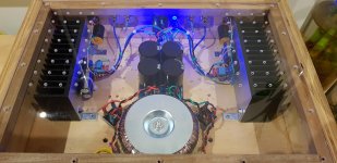
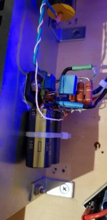
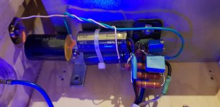
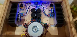
I built this amp a couple of years ago P2P, worked fine but never managed to house it in a proper case, it was left on the bench gathering dust due to lack of fund for heatsinks and power supply. Last week my usual listen-to amp decided to send a full rail of DC to one side of speaker when I switched it on one morning, luckily it's only for 1 or so second before I turn it off. I am not sure if the MA Alpair 7.3 is damaged, it plays fine though, I measured the DC resistance and it's way off spec, only 4.3 ohm, the one didn't cope the full DC measured 5.6ohm as per spec.
Anyway, instead of fixing it I decided to put Joe's TC Amp in this case and utilise the heatsinks. I also decided to use only 1 transformer and 1 CRC power supply to power both channels instead of dual mono.
It sounds very different, it's like having a new set of speakers. My frugel horns used to sound thin and paper weight, now it feels punchy and meaty, like having a big fat burger topped with a thick layer of melted mozzarella cheese if you know what I mean. I can't tell if it has wider sound stage as my set of frugal horn has very narrow sound stage (in between 2 speakers), as for the depth I need a binocular with this amp.
It's the quietest amp I have ever built, with input shorted to ground, there is no hum, no buzz, no nothing. I have my ear basically touching the cone of the Alpair 7.3 and couldn't hear a thing. In comparison my dual mono 3886 used to have a very faint hiss with my ear touching the speaker cone. DC Offset is dead 0 with speakers connected, I also don't have the start-up or shut down thump issue as other encountered. It's definitely a keeper for sure.
Attachments
Interesting characterisation of the change in sound.  My open baffle dipole sounded similar - thin and too much up top. Can't comment on soundstage yet, as I have only built the one, but now eager to build the second to test width and depth.
Also interesting is your comment about input shorted to ground. Turning off the system last night one by one, all components upstream of the amp, the buzz lessened each time, until there was no buzz, only a slight hiss with ear right next to the speaker when only the amp was left on. Will disconnect SG off the amp board tonight and connect straight to chassis ground.
Great job on your amp.
My open baffle dipole sounded similar - thin and too much up top. Can't comment on soundstage yet, as I have only built the one, but now eager to build the second to test width and depth.Also interesting is your comment about input shorted to ground. Turning off the system last night one by one, all components upstream of the amp, the buzz lessened each time, until there was no buzz, only a slight hiss with ear right next to the speaker when only the amp was left on. Will disconnect SG off the amp board tonight and connect straight to chassis ground.
Great job on your amp.
would you mind sending picture with detailed connections? This will be helpful for many people.
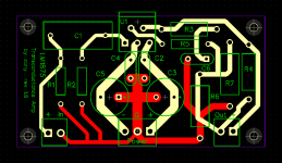
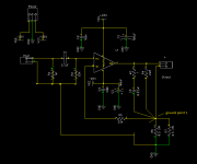
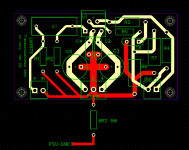
I have redesigned the pcb removing the ground plane and containing the ground currents to the caps. Schematic is the same as original. Board stuffed and connected, I noticed a slight reduction in buzzing, but still present. I have a spare board - this one will be stuffed in the next few days with the suggestions from augustoriodosul and jameshillj as in the following screenshot.
I'm curious regarding the performance differences of these three iterations and am looking forward to taking some measurements.
Attachments
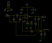
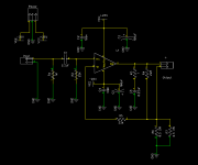
Ok, no simulations or measurements yet, but plenty of experimenting. I connected both channels of the amp to my regular speakers. Very loud buzzing when the buffer preamp is on, very quiet when the buffer is powered off. When the buffer is disconnected, shorting the interconnect with my fingertips creates loud buzzing again. One channel has been modified as shown having tried the suggestions given earlier in this thread - no luck, in fact, the buzzing is now louder. . Also, an 8R2 5W resistor (didn't have 22R) has been added from power supply ground to chassis ground as shown in schematic by EmeryBB and Joe in post #1. As a point of reference, my ACA amp has no noise when used with the buffer. Next option is to try an isolation transformer between buffer and amp.
Attachments
Finally resolved the buzz issue. Arifs' post had the answer.
hum with RCA
An 8R2 5W resistor from amp pcb gnd to psu gnd on both channels reduced the buzz to a very low hum with ear on speaker. Happy days! Thanks to all for assisting. Now, time to enjoy some current drive goodness.
hum with RCA
An 8R2 5W resistor from amp pcb gnd to psu gnd on both channels reduced the buzz to a very low hum with ear on speaker. Happy days! Thanks to all for assisting. Now, time to enjoy some current drive goodness.
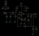
Great job mate. That's pretty much what I did. The schematic I posted earlier is really the stock schematic from Joe's except I have added a 10R resistor to isolate the low current signal ground from high current ground. If I remember correctly it was our late AndrewT suggested this type grounding method. I use this grounding in all my amps and it works like a champ.
The other thing I've done recently is removed the 22R to chassis. I find it doesn't make any difference in terms of hum noise. Personally I think it's dangerous to have that resistor there especially if one is using a metal chassis. Either use Rod Elliott ground lifting diode or just a piece of wire.
The other thing I've done recently is removed the 22R to chassis. I find it doesn't make any difference in terms of hum noise. Personally I think it's dangerous to have that resistor there especially if one is using a metal chassis. Either use Rod Elliott ground lifting diode or just a piece of wire.
Last edited:
Thanks mate. Due to the pcb, I couldn't place the resistor where you put it. I tried it on the signal ground wire into the pcb but didnt work. I put it here.
I also tried the resistor from psu gnd to earth gnd. Removed it when, like you, it made no difference. I have reinstalled the wire.
I also tried the resistor from psu gnd to earth gnd. Removed it when, like you, it made no difference. I have reinstalled the wire.
Attachments
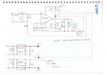
Change AB class voltage amp to transcondutance?
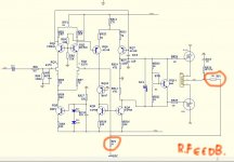
Hello all, a little help: mimesis Chinese clone schematic figure M1 (JIM AUDIO), lateral mosfets AB class. According to Current-Driving of Loudspeakers by Esa Meriläinen, it is possible to transform any amp into transconductance. I tried some paths, as in the link (FAQ about current-drive | Current-Drive - The Natural Way of Loudspeaker Operation) - Can existing power amplifiers be modified to give current output?? When you turn on amp with mod it lights up the lamp in series indicating serious problem. Anyone specializing in this forum could help designing how to connect network feedback and sense resistor (.33R * 5W) to get an amp transconductance? Thank you.
Hello all, a little help: mimesis Chinese clone schematic figure M1 (JIM AUDIO), lateral mosfets AB class. According to Current-Driving of Loudspeakers by Esa Meriläinen, it is possible to transform any amp into transconductance. I tried some paths, as in the link (FAQ about current-drive | Current-Drive - The Natural Way of Loudspeaker Operation) - Can existing power amplifiers be modified to give current output?? When you turn on amp with mod it lights up the lamp in series indicating serious problem. Anyone specializing in this forum could help designing how to connect network feedback and sense resistor (.33R * 5W) to get an amp transconductance? Thank you.
Attachments
Last edited:
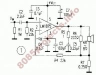
Based on my experienced, The sound of TDA2030 or TDA2050 better than LM3875.
I have 5 transductance amplifiers.
There are TDA2030,TDA2050,LM1875,LM3875 and TDA7294.
@Danuphonj, would you mind sharing the schematics to your amps? I am very interested
Hi Dave (Planet 10),
what should be the sweet Qms value?
On what grounds and physical parameters? Would SPL response linearize itself at a given Qms? Assume that current source and thermal system capabilities are is not a parameter (assume all operating conditions possible) and we really do not discuss them it in this question.
Thanks,
Better, if possible, please PM.
- Home
- Amplifiers
- Chip Amps
- Joe Rasmussen "Trans-Amp" - 40 Watt Transconductance "Current Amplifier"