Damping is usually thought of in terms of a resonator which is critically damped with a resistance equal to it's characteristic impedance Zo=sqrt(L/C). Mechanical resonators can be thought of the same way.
Resonators are also good antennas, so yes there is an aspect of interference.
For a parallel resonator, which is what the speaker's electrodynamic impedance is, a parallel resistance increases damping whereas a series resistance limits it.
Most speakers are designed so that they can never be overdamped due to what is driving the speaker, so the coil resistance is about equal to the Zo of the electrodynamic resonance at Fs.
I fail to see what makes this special or exclusive knowledge.
I can understand what is being said, but I fail to see any measurement that relates with improving sound quality?
I can understand what is being said, but I fail to see any measurement that relates with improving sound quality?
Me too, I don't see any new information being shared, just a continual insistence that we don't understand.

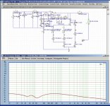
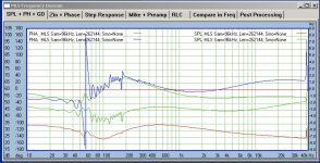
This is an example of how I would do a measurement (red curve data taken from the point after the 100mohm resistor at the opamp output)
Basically, the lower the red curve is, the better clarity in sound. The shape of the curve would be somewhat at inversion of the driver impedance. Sometimes the higher frequency end may have an upward trend deviating from the expected. This means some mod in the amp design is necessary.
Basically, the lower the red curve is, the better clarity in sound. The shape of the curve would be somewhat at inversion of the driver impedance. Sometimes the higher frequency end may have an upward trend deviating from the expected. This means some mod in the amp design is necessary.
Attachments
You'll be waiting for ever for Joe to show anything.I can understand what is being said, but I fail to see any measurement that relates with improving sound quality?
Looking at that, I would flatten the speaker impedance as Joe does. Yes, the result is some audible improvement.Post 595?
Jan
What I meant was that speakers on the market are designed with voltage drive (an amp with very low Zout) in mind. I agree you can design a speaker for current drive, and probably for very good performance.
My gut feeling, not proven, is that because of the dualism between voltage and current, you can probably design speakers and amps based either on voltage drive or current drive with comparable cost and performance.
But it won't happen because of sunk investments in speakers for voltage drive.
Do you know any speakers designed for current drive?
Jan
There is none that I know such a clear defined "designed for CS" driver. Ask Planet10 for more examples. But, in my opinion, there is no real need for such special design. Most normal drivers are just fine, with proper additions and mitigations. If you do not need a true ultra high-end performance, then rocket science specialists and deep pockets are not needed for your project.
For current source I would choose any standard LF driver of your acoustical taste and choice (internal XO-stripped out from start):
1. which allows cooling of magnet, if needed
2. which has sufficient cooling of voicecoil
3. I would install a simple but reliable temperature sensing (switch off)
To satisfy 1+2 probably any LF driver designed for 400W will be fine for a 60W current source.
Additionally, I would shape the freq. characteristic around Fr of driver: careful and midful of phases. This step, done properly, will mitigate most part of the #1-#3 issues.
Against the usual trends and recommendation, in my personal-taste wise I would choose a fast (light) driver with as high efficiency as possible. A mid-Q driver makes it easier to fix the problems. An expensive ceramic magnet helps a lot. I would avoid Fe-magnets and NFeB ones. Last but not least, the sicke should be stiff, to limit X-max, combined with a long air gap.
This list is not final nor fixed. Just some list of examples for targets, options and milestones.
This full-range driver technique described by Nelson Pass is about EQ, which is not what we are talking about here.There is none that I know such a clear defined "designed for CS" driver. Ask Planet10 for more examples.
That could mean frequency response, gain linearity, or instantaneous accuracy, maybe you should be more specific.
There is no reason a voltage drive system couldn't have the same frequency response as a current drive system. However if you understand the parent function of the distortion mechanisms maybe it would be possible to infer based on the distortion spectrum.
The presence of thermal compression could also be an indicator.
Are you implying that, for instance, ALL current driven systems have less thermal compression than ALL voltage driven systems? Only then can it be used as some kind of identifier.
I know a couple of successful speaker system designers, voltage driven, who are quite considerate of thermal compression.
I guess you see where I am going here. ;-)
Jan
I know a couple of successful speaker system designers, voltage driven, who are quite considerate of thermal compression.
I guess you see where I am going here. ;-)
Jan
Last edited:
Is this about the Norton/Thevenin equivalence thing you brought up earlier?
The nonlinearity in a speaker does not follow equivalence. Voltage drive allows the speaker to modulate it's own coil current whereas current drive does not. This causes a difference in transfer function between current and voltage drive.
The nonlinearity in a speaker does not follow equivalence. Voltage drive allows the speaker to modulate it's own coil current whereas current drive does not. This causes a difference in transfer function between current and voltage drive.
Yes, I said the nonlinearity does not follow equivalence, for the linear part there is equivalence.
1% distortion could cause 1% gain linearity more or less, depending on how you measure gain, whether it is average, RMS, or peak. Any change in phase would be a similar fraction of the total phase, IE very small. But the addition or subtraction of a harmonic cannot change the phase of the fundamental. Only the addition or subtraction at the fundamental frequency can change it's phase.
I think I determined at some point through some pretty questionable math that the motor generates a subharmonic of the 2nd harmonic at the fundamental frequency, and maybe this could affect the fundamental phase. But I think that was actually for voltage drive, not current drive. Still, it would be a difference. But I know better than to trust my math skills.
Edit: Here is the post:
John Curl's Blowtorch preamplifier part III
I'm sure this is riddled with errors, for instance the reluctance force should attract the voicecoil rather than repel it (which is what eddy currents do). But, if there is a subharmonic of a harmonic that occurs at the fundamental frequency, then that could potentially cause phase shift.
Which would account for the differences in distortion? Seems to me it could also cause different phase shifts at different frequencies?
1% distortion could cause 1% gain linearity more or less, depending on how you measure gain, whether it is average, RMS, or peak. Any change in phase would be a similar fraction of the total phase, IE very small. But the addition or subtraction of a harmonic cannot change the phase of the fundamental. Only the addition or subtraction at the fundamental frequency can change it's phase.
I think I determined at some point through some pretty questionable math that the motor generates a subharmonic of the 2nd harmonic at the fundamental frequency, and maybe this could affect the fundamental phase. But I think that was actually for voltage drive, not current drive. Still, it would be a difference. But I know better than to trust my math skills.
Edit: Here is the post:
John Curl's Blowtorch preamplifier part III
So the linear component of Le(x) only causes a 2nd harmonic whose DC component tries to push the coil out of the magnet. Oddly enough a second harmonic in the Le(x) function itself actually causes a subharmonic of itself in the Reluctance force, at the fundamental frequency. This is a nonlinear mixer where it seems a lot of weird stuff can happen.
I'm sure this is riddled with errors, for instance the reluctance force should attract the voicecoil rather than repel it (which is what eddy currents do). But, if there is a subharmonic of a harmonic that occurs at the fundamental frequency, then that could potentially cause phase shift.
Last edited:
The problem isn't technical, it is marketing. Making amps voltage sources gives speaker designers a known source, with which their drivers should work.
If you design a current drive amp, you just can't use any speaker and expect it to work well.
Exactly. And given the dominance of boring sounding SS voltage source amplifiers, most people do not have any idea how the impedance response of the loudspeaker can affect its frequency response.
So to take advantage of the (purported) advantages of current driver one is often best left looking at the very speakers with flat impedance curves (ie Elsinore, La Scala with Crites XO), many fullranges, and in multi-amped systems where the drivers have flat impedance within their bandwidth.
Probably of more import is dealing with the much more common and growing segment of high Rout amplifiers that are still technically on the voltage source side of the chart, but getting close to the border, typically SETs, but we are seeing a growing number of SS amps where consideration of the effect of speaker impedance start imposing themselves (ie ACA, VFET, F2).
This is not a bad thing, it is just a different set of compromises and someone with greater understanding ptting the system together.
dave
- Home
- Amplifiers
- Chip Amps
- Joe Rasmussen "Trans-Amp" - 40 Watt Transconductance "Current Amplifier"