Ok, A little research told me what is an impedance plot. Sorry for my not perfect understanding of english language. But I would like to know how do you measure it.
There are of course tool that do the job, but a reasonable accurate AC meter and a signal generator is needed. We are mostly concerned with below 100 Hertz. You can also get CDs with test tones. Use a 4R to 10R resistor, adjust level to 1V RMS and take readings below 100 Hertz, and provided that it stays reasonable close to 1V RMS below 100 Hertz at different frequencies, then all is OK.
(For others reading this, the Elsinores have a much flatter impedance below 100 Hertz than almost any other speaker around - if it was put together properly.)
If the meter is accurate to higher frequencies, then you can measure that too, but below 100 Hertz is the most important.
The signal generator can even be a smart phone with a suitable app for iPhone or Android.
There are some YouTube videos, check them out.
Cheers, Joe
.
Last edited:
Hi Joe. I'm looking on with much interest. I see two PCB's in there. Are they specific for the LM3875? i.e. are they just breakouts of the I.C. pins? If so how can I obtain them. Ultimately I'd to a complete PCB layout with Protel but initially those would get it up and running. I'm already thinking of chassis layouts. Hmmm. (Still loving my Elsinore's)
Nice Joe. I did almost the exact same thing two years ago with either the LM3875 or 3886, I don't remember which. I did a P2P with an old Gainclone and rewired it as a standard V to I converter. My sense resistor was a bundle of ten 10 ohm resistors in parallel- 1 ohm made the calculations easier. What I found was that they are very speaker dependent - you have to use fullrange drivers and small ones can easily run out of excursion around the resonant frequency. They do sound different, I think the rising impedance with frequency puts more power into the high frequencies of a driver with a current amp, whereas a voltage amp puts in less. So there's a differing frequency response.
The amp sounded fine, but I retired it as an experiment. I just don't like what happens if a speaker wire is accidentally unplugged or there is a dodgy connection while the amp is on. Maybe for a hardwired subwoofer this could be interesting.
The amp sounded fine, but I retired it as an experiment. I just don't like what happens if a speaker wire is accidentally unplugged or there is a dodgy connection while the amp is on. Maybe for a hardwired subwoofer this could be interesting.
What I found was that they are very speaker dependent - you have to use fullrange drivers and small ones can easily run out of excursion around the resonant frequency. They do sound different, I think the rising impedance with frequency puts more power into the high frequencies of a driver with a current amp, whereas a voltage amp puts in less. So there's a differing frequency response.
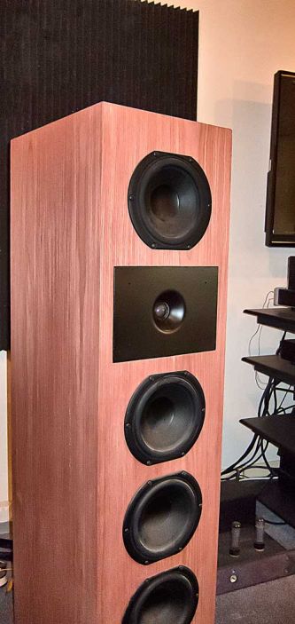
Take a look at this:
This is the Elsinore Mk5 speakers, not a problem.
Cheers, Joe
Any thoughts on using this, or something like it, to directly drive a ribbon (impedance ~ .1 ohm). What is the limiting factor in the amount of current it can drive?
Nelson Pass talks on his DIY web site about a high current transconductance amp that he tested on tweeters.
The current limit will be a function of safe operating area of the chip and emitter resistors in the final stage of the chip.
My gut tells me that the lowest voltage rails that allow operation will be the best since your output voltage will be just a couple of volts if even that.
Your tweeter will look like a short circuit to the amp. Your cables may have more DC resistance than the tweeter.
Any thoughts on using this, or something like it, to directly drive a ribbon (impedance ~ .1 ohm). What is the limiting factor in the amount of current it can drive?
I would highly not recommend driving a ribbon with a transconductance amplifier. Tweeters and especially ribbons are voltage devices requiring very little current to drive them. Similar question was posed to me eons ago (~25 years or so) and devised a test to prove my point. It was winter in Ohio and as we all know static can be an issue if the humidity level drops too low. So I took a woofer and a tweeter and earth grounded the negative terminal, no crossover, just raw drivers. Then shuffled across the floor in my silk socks and touched the unconnected terminal of the woofer. Nothing, except the spark jumping the gap. Now for the tweeter, a very sharp crack could be heard. Since static electricity has ultra low current, the woofer couldn't be excited, but on the flipside the tweeter reacted as predicted, proving the point.
I would highly not recommend driving a ribbon with a transconductance amplifier. Tweeters and especially ribbons are voltage devices requiring very little current to drive them. Similar question was posed to me eons ago (~25 years or so) and devised a test to prove my point. It was winter in Ohio and as we all know static can be an issue if the humidity level drops too low. So I took a woofer and a tweeter and earth grounded the negative terminal, no crossover, just raw drivers. Then shuffled across the floor in my silk socks and touched the unconnected terminal of the woofer. Nothing, except the spark jumping the gap. Now for the tweeter, a very sharp crack could be heard. Since static electricity has ultra low current, the woofer couldn't be excited, but on the flipside the tweeter reacted as predicted, proving the point.
I believe that your experiment proved something about the mass of the ribbon compared to the mass of the woofer and did not prove anything about voltage or current.
A ribbon is driven just like a woofer; force is equal to BL time Current.
For a 0.1 ohm ribbon, 10 amps would be at 1 volt; V = I * R. I doubt very much that the ribbon discussed here can handle 10 amps.
I have built a 6 foot tall true ribbon and a 1.5 V battery caused the ribbon to jump out of the gap.
OP, if you can get 2 to 3 amps through your ribbon I believe that you will have more than enough. The limit of the current will be the chip, the wiring and the circuit design.
Surface area x mass is proportional to current for any given BL, especially so with an ultra low impedance driver like yours. I see no problem with that. But it's not a tweeter nor does it have the typical impedance of 4-8Ω
0.1Ω is a current shunt, which due to it's exceedingly low resistance requires current to drive, not voltage. In this case I would say a transconductance amplifier transformer coupled is right up your alley.
When we make comparisons it should be done apples to apples, not apples to watermellons or monster size pumpkins.")
0.1Ω is a current shunt, which due to it's exceedingly low resistance requires current to drive, not voltage. In this case I would say a transconductance amplifier transformer coupled is right up your alley.
When we make comparisons it should be done apples to apples, not apples to watermellons or monster size pumpkins.
Hi Joe. I'm looking on with much interest. I see two PCB's in there... (Still loving my Elsinore's)
Alas, those PCB were leftovers from the JLTi Mk2 amplifier built some 8 years ago - and they had to be 'cut up' in a number of ways track wise. Not going to supply any.
Cheers, Joe
.
Have you measured the output impedance of the amplifier? Are you shooting for a particular amplifier output impedance?
The perfect transconductance amplifier (a "current follower") should have an infinitely high output impedance, whereas a conventional voltage amplifier (a "voltage follower") should have infinitely low or zero output impedance. Since neither is practicable, the aim should either be as high as possible, or as low as possible, respectively.
Think about it, with current out, to be tracking perfectly, if producing 1V RMS into 4 Ohm and then exactly double 2V RMS into 8 Ohm, that can only happen if the output impedance was infinitely high. Do the maths.
In our example, where the output Z is 270 Ohm (which is high for a "power current follower"), then 1V RMS into 4 Ohm produces, in our case, 1.962V into 8 Ohm. If the output impedance had been infinite, it would have produced the full 2V.
Cheers, Joe
.
I would highly not recommend driving a ribbon with a transconductance amplifier...
Certainly not if it is 0.1 Ohm - not with this design.
The SOA of the LM3875 and the current limiting would prevent that (the LM3875 will overheat and gradually shut itself down - I have experienced this event). I would not recommend any load below 3 Ohm with this design. The same limitations exists, whether current or voltage out.
But having said that, a ribbon works very well when current driven, just need to take real world situations into account. Transformers used with ribbons also work well as current transformers as current transformers.
One thing that is often overlooked with current output amplifiers, is that the current phase angle is always zero.
Irrespectively of the load.
Certainly, both ribbons and conventional dynamic (coil and magnet) drivers, are in fact current devices - they turn current into motion, not voltage into motion. They track current, not voltage. The zero degree current phase angle means better current tracking, less phase noise... less... jitter.
Cheers, Joe
.
Last edited:
One thing that is often overlooked with current output amplifiers, is that the current phase angle is always zero.
Irrespectively of the load.
Certainly, both ribbons and conventional dynamic (coil and magnet) drivers, are in fact current devices - they turn current into motion, not voltage into motion. They track current, not voltage. The zero degree current phase angle means better current tracking, less phase noise... less... jitter.
Cheers, Joe
.
Hi Joe
If you make a PCB of this design I would like to get one and build it. I am keenly interested in current drive of speakers and I think that the chip amps are a good way to get 2 to 3 amps into a speaker at resonance without heroic costs.
I have bootstrapped a Crown amp by driving it with an op using the circuit you have posted here. I used it to create 3 amps at resonance into a beefy car audio speaker capable of 3 inches pk-pk excursion.
Hi Joe,
Thanks for sharing the schematics.
I'm very interested in building a transconductance amp, ever since I bought "Current driving of loudspeakers" and happenned to stumble upon your Elsinore project page.
The fact that this build seems pretty straightforward and requires a low component count and a relatively small PS makes it attractive.
Just a few questions though:
How hard would it be to build a Point 2 point version of the circuit? Any pitfalls to avoid?
What is a reliable source for LM3875 chips?
Thanks
Nick
Variable Amplifier Impedance
Hi Joe,
I would be interseted by mixed mode feedback mixed mode feedback
Did you ever tried to replace the 470 resistor by a pot to find the sweet spot for your loudspeakers?
Thanks,
Nicolas
Hi Joe,
I would be interseted by mixed mode feedback mixed mode feedback
Did you ever tried to replace the 470 resistor by a pot to find the sweet spot for your loudspeakers?
Thanks,
Nicolas
Joe, wondered why you left off the output filter that prevents ringing with capacitive loads. Unnecessary unless using this type of load...Or just slap on a 0.7uH in parallel with a 10Ω in series...
My gut feeling is that it is not needed. Maybe more than gut feeling, as with that high Output Z the current phase angle just won't budge, so that makes it very much load insensitive.
Could try R/C reactive load and see what happens, but clearly the output will just drop when the capacitor's reactance gets less than the R value and cannot rise, fact will do the opposite. So an amplifier of this type is hard to get unstable. The cap part will just act as a first order filter, but also the amp's output will just drop as well (OTOH, a voltage amp would try to maintain the level and hence potentially run into trouble). No energy, no instability, zero current phase shift...
Current output amplifiers behave so differently and because most don't have experience with them, their behaviour can seem positively strange.
But layout can definite affect stability, but get that right and it should be OK.
Cheers, Joe
Last edited:
Hi Joe, Nice amp!This is the one I built. I uses only a single 300VA transformer, but I don't recommend it. It was very tricky indeed. Best to go with separate transformers, or be prepared to sort out some issues.
. . .
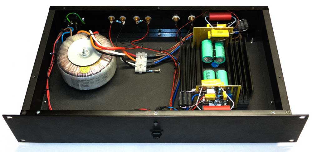
What do you think of sending DC to the amplifier boards, like this? <--link (see the photos)
That diode isolation system (virtual dual mono), plus a 5x2200u per rail simple supply for DC (just one supply), would not disturb your cable layout much, except for the difference of sending DC to the amplifier boards instead of AC. Cleaner power might make the layout task easier.
It is possible that you may find virtual dual mono power to be an interesting experiment for tone, clarity, depth and imaging.
I don't see that a modification is necessary; however, the photo shows a handy stereo amplifier conveniently with the cover off.
P.S.
Thank you for making a chip amplifier suited to full range speaker drivers!
Last edited:
Thank you very much for posting your schematics here.
Encouraged by the substantial decrease in both harmonic and intermodular distortion I measured when driving several different drivers with a series resistor (20 to 90 ohms with a 300W class D amplifier) I tried to follow your instructions and wiring scheme. My idea is to drive my actively crossed upper midrange drivers with a current source amplifier way above the resonance frequency domain.
When connected to a 4 ohm dummy load with no input I measured 22V across the load and had to turn it off quickly due to the power dissipation - I used the light bulb trick (2 X 40W) - that lit up the room. Of course I could have made a mistake, but after several checks the wiring seems to be OK - not that any mistakes can ruled out by that of course.
You write one should null the output - is that the problem? And if so, could you - or someone else reading - this please help the chemist out? I'm very much a novice when it comes to circuitry.
Regards
Encouraged by the substantial decrease in both harmonic and intermodular distortion I measured when driving several different drivers with a series resistor (20 to 90 ohms with a 300W class D amplifier) I tried to follow your instructions and wiring scheme. My idea is to drive my actively crossed upper midrange drivers with a current source amplifier way above the resonance frequency domain.
When connected to a 4 ohm dummy load with no input I measured 22V across the load and had to turn it off quickly due to the power dissipation - I used the light bulb trick (2 X 40W) - that lit up the room.
Of course I could have made a mistake, but after several checks the wiring seems to be OK - not that any mistakes can ruled out by that of course. You write one should null the output - is that the problem? And if so, could you - or someone else reading - this please help the chemist out? I'm very much a novice when it comes to circuitry.
Regards
Last edited:
- Home
- Amplifiers
- Chip Amps
- Joe Rasmussen "Trans-Amp" - 40 Watt Transconductance "Current Amplifier"