I have another question.
At present I am using only one transformer for all the 6 set of LM3886 chips.
I just added the 3 way active X over with a 100K dual volume control in front of it.
The X-over is getting its power from a 20-0-20 Vac tapping from the same transformer.
It has a built in +-15V regulated supply on board which is giving +16.8 and -16.2 Vdc.
I'm using an Mp3 player with some 320 kbps test samples. I tested with some Flac Samples too.
When I removed the Lamp in series I see the following.
The big heat sinks can handle the heat very well now.
The output is very clean and in fact way more than enough for my listening room.
It even damaged a tweeter with its high output due to a silly mistake of mine.
Bass response is very very good. Excellent Mid range. Great sound stage/ stereo imaging.
No hum, hiss or any kind of distortion.
The transformer alone can handle all the amps with X-over for my personal requirements as it seems .
Do I still need to use the other transformer and the those 6 X 4700 uFd caps for the second channel?
Will there be a great difference in sound quality even a low volume if I use the individual PSU for each channel?
Kindly explain.
Thank you.
Last edited:
Depends on whether you plan to house the electronics in the speaker boxes or not.Do I still need to use the other transformer and the those 6 X 4700 uFd caps for the second channel?
No, and anyone who says otherwise has an over-active imagination.Will there be a great difference in sound quality even a low volume if I use the individual PSU for each channel?
I will post pics in the next few days. They are not attractive but that isn't important.
Last edited:
There shouldn't be a GREAT difference in sound quality just from using one transformer instead of two. There might be a little.
But you will probably only be able to get 50 or 60 watts output, TOTAL, with only one of those transformers. Amplifiers like these are usually not too much more than 60-something percent efficient. The rest goes out through the heatsinks. And only one rail plays at a time, with push-pull (class AB) amps.
So if you get enough output power with one, then it's fine. But make sure that you will be satisfied with the maximum output power level when using only one transformer to power both channels. Also, clipping might occur much more easily, if there's not enough power available. That can damage tweeters. You might need to use all of the caps from the other transformer, too, with the one that you use, to mitigate the clipping potential, depending on how loud you might want to have it and how you have everything configured (Too lazy to look, right now. Sorry.) I think that I would prefer to have power available that I never used, rather than possibly not having enough, unless I needed the other transformer for something else.
I would recommend using a small, separate transformer for the XO board. I suspect the majority of any ground issues will be linked to using a tapped secondary for a low level circuit, unless it is a totally separated winding.
I have successfully powered five amplifier circuits off one transformer but the grounding ended up being a lot more complex than I imagined. This is for a surround amplifier with a total of seven amplifier chips and a mix of chips and topologies - a parts bin project, if you will.
I had to route each power ground separately, and the input grounds were even more complex given they were coming in from outside the chassis from a computer soundcard - not the nicest source. All the output grounds are returned to the power ground instead of the chip outputs to help me a bit, and this worked well. I have 3 LM3886, two 1875 and two OPA549s in bridge mode for a sub in one little box. It's a miracle it even works
no.Thank you sir.
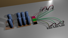
I tried my best as I understood from your direction . Kindly have a look.
Done.
Done too sir.
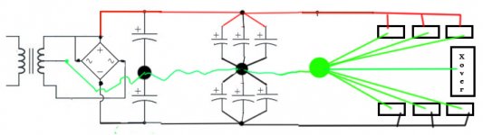
The first pair of caps take the biggest charging pulse.
This circuit: transformer to rectifier to cap pair MUST be separate from the next stage of smoothing.
Use ONE wire link from first stage smoothing to second stage.
The use ONE wire from second stage to Main Audio Ground.
DO NOT put the Main Audio Ground between the smoothing caps.
Last edited:
Two sets of 3channel active amplifiers can easily tick over from a 200VA transformer. 6channels of 70mA quiescent equals ~420mA.
A 200VA 25-0-25 has a maximum continuous DC capability of 2Adc.
420mA is just 21% of it's continuous capability.
It's what happens if you can get some of these amps running at near maximum power that a smaller than optimum transformer will show significant voltage sag.
Assume the bass amps are giving 50W and the mids amps are giving 30W and the treble amps are giving 10W on a prolonged peak, but the average is 6dB lower than that.
The total peak load on the 200VA transformer is 2*(50+30+10) * 1.5 for amp efficiency i.e. ~270W peak during the crescendo and returning to your average of ~80W. The transformer can easily manage that.
The smoothing capacitors meet the peak demand. The transformer recharges them.
However I always recommend locating the amplifiers at the speakers.
An active system benefits from this even more, since you are now shortening 6pairs of speaker cables. Two 200VA located as two 3channel amplifiers at the speakers makes more sense. I would not put them in the speakers. Too much vibration.
Last edited:
I did, three years ago, and have not had a single problem since. I understand the concern but it is, I believe, overstated. if you are worried, put the electronics mounting plate (I used 3mm aluminium) on some foam.I would not put them in the speakers. Too much vibration.
Each of those speakers uses a 160VA toroidal transformer, about 40VA less than yours, to run the three amps (in one box, there are four because the woofer runs bridged), the crossover, speaker protectors and the balanced driver for the bridged amps. I have not ever been short of power, never. It can play loud enough to be heard loudly 40 metres away. So I re-iterate what I said in post 23, you will not experience any shortage of volume, assuming drivers with 87 to 90 dB/W sensitivity. Mine can play deafeningly loud when the mood or beverage causes an interest in loud rock.
Generally though, you won't play them loud all the time because they will disturb your neighbours too much. What gootee has overlooked is that the amps drive the speakers directly and there is no loss, as in a passive crossover. If mine can do this with 160VA, 200VA will be more than enough.
Yes, you are correct that I did not consider that a line level crossover might make a difference in available power. My main concern was that there might not be enough power to go loud enough without clipping, if using only one transformer to power all six amplifiers. But since he can simply test it and see, first, I still think he should just test it and find out.
Last edited:
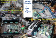
Work in progress
This is the update of my work.
1. caps around the rectifier removed now. No problem, no perceptible change in the sound quality, no hum, hiss or any disruption.
2. Each amp is connected to a common connecting point with heavily twisted wires using insulating tubes.
3. Now connecting the amps to directly to the AC 220V. Removed the bulb in series. Pretty loud thundering output with exceptional clarity even with one four amp transformer and 6 X 4700 uFd.
when the bulb is in series with six amps, the amps are not working now but with direct connection from the mains, the sound is magical.
No clipping at all when the volume ( 100K dual Volume control ) is at the maximum position. I have not used the preamp this time. Just connected the output from an MP3 player (with maximum volume) to the input of the X-over.
But I have more questions/ doubts. So to all, kindly get in touch.
Thank you.
Attachments
Thank you so much! Please take your time.Depends on whether you plan to house the electronics in the speaker boxes or not.
No, and anyone who says otherwise has an over-active imagination.
I will post pics in the next few days. They are not attractive but that isn't important.
Thank you so much Gootee for your comment.There shouldn't be a GREAT difference in sound quality just from using one transformer instead of two. There might be a little..........................
...............................So if you get enough output power with one, then it's fine. But make sure that you will be satisfied with the maximum output power level when using only one transformer to power both channels. Also, clipping might occur much more easily, if there's not enough power available. That can damage tweeters. You might need to use all of the caps from the other transformer, too, with the one that you use, to mitigate the clipping potential, depending on how loud you might want to have it .
If I use those 6 X 4700 uFd caps along the existing 6 pieces what can be the expected DC voltage?
How to calculate the DC voltage both with and without Load?
And will it be safe to feed the amps? Or LM3886 has a over voltage protection in built?
Is not LM3886 equipped with under voltage protection too?
What is the cause of the tweeters getting damaged? Oscillation ?
I thought one of my tweeters was damaged due to high output.
I would recommend using a small, separate transformer for the XO board. I suspect the majority of any ground issues will be linked to using a tapped secondary for a low level circuit, unless it is a totally separated winding.
Thank you Sangram, for your input and sharing your experience.
As you know a good toroidal transformer and good speakers are ALMOST beyond the scope of average Indian Hobbyists like myself.
I was really angry when I saw the transformer manufacturer has not used a separate winding for the auxiliary ac output. But fortunately the X-over I built earlier handled the problem well. No hum even when the X-over levels are full.
Now I am planning to make the preamp/ Eq etc. in a separate metal cabinet.
I am learning from the words from the audio gurus. I am happy that you all are interested in my project. So all, please feel free to comment/ suggest/ guide.
no.
The first pair of caps take the biggest charging pulse.
This circuit: transformer to rectifier to cap pair MUST be separate from the next stage of smoothing.
Use ONE wire link from first stage smoothing to second stage.
The use ONE wire from second stage to Main Audio Ground.
DO NOT put the Main Audio Ground between the smoothing caps.
Thank you sir.
Posting my another effort ( expecting a "no" again)
Kindly have a look.
Attachments

Generally though, you won't play them loud all the time because they will disturb your neighbours too much. ....................... If mine can do this with 160VA, 200VA will be more than enough.
Very well thought out words.
Same problem here. I can't play loud as this might disturb my neighbours.
I just need all the rich, crystal clear, finer details and a great sound stage/ stereo image at low volume.
Last edited:
yes.Thank you sir.
Posting my another effort ( expecting a "no" again)
Kindly have a look.
yes.
Thank you Sir.
It is +-33.5 VDC now with 6 set of caps now.
Can I add two more 4700uFd caps at the second stage of the PSU?
Will the voltage be under safe operating limit then?
( LM3886 datasheet is not very legible to my level of intelligence).
Attachments
Last edited:
I was just counting the amper requirements.
50+30+10W doesn't require the same amp as 90W.
It needs less voltage and more amp. about 2x 4.5A. 2x26v 200VA trafo doesn't have it. Also no headroom. With 2 trafo I would say enough.
As I said:
Each of those speakers uses a 160VA toroidal transformer, about 40VA less than yours, to run the three amps (in one box, there are four because the woofer runs bridged), the crossover, speaker protectors and the balanced driver for the bridged amps. I have not ever been short of power, never. It can play loud enough to be heard loudly 40 metres away. So I re-iterate what I said in post 23, you will not experience any shortage of volume, assuming drivers with 87 to 90 dB/W sensitivity. Mine can play deafeningly loud when the mood or beverage causes an interest in loud rock.
Generally though, you won't play them loud all the time because they will disturb your neighbours too much. What gootee has overlooked is that the amps drive the speakers directly and there is no loss, as in a passive crossover. If mine can do this with 160VA, 200VA will be more than enough.
Yes, but there is a point of diminishing returns, ie, you won't get much, if any benefit, from the added caps. If you are going to use the all the caps, I would divide them between the speaker cabinets; two per rail for each box, if you have eight. I use two x 4,700 caps per rail and, if there is any voltage sag, I can't hear it. (Mainly because, at that volume, I can't hear anything but the music, not even my own thoughts.Can I add two more 4700uFd caps at the second stage of the PSU?
)Yes. More caps does not affect the rail voltages, it only provides extra current when needed.Will the voltage be under safe operating limit then?
Last edited:
The unloaded PSU voltage is fixed at +/-33.5 VDC, at which the LM3886 datasheet gives the clipping voltage as 2.75 Volts.
With 50 Hz AC Mains supply, the rectifier charging period is 0.01 second.
(1) I = C dv/dt
The peak-to-peak ripple voltage would be dv:
(2) dv = I∙dt / C
But we also know that the maximum peak output voltage, at the onset of clipping, would be:
(3) Voutpk = Vrail - Vclip - dv
and at that point
(4) I = Voutpk / Rload
Also, the longest discharge time would make
(5) dt = 1 / (2∙fmains)
If we substitute (3) into (4):
(6) I = (Vrail - Vclip - dv) / Rload
If we substitute (6) into (2):
(7) dv = [ (Vrail - Vclip - dv) / Rload ] ( dt / C )
Then we can solve for the p-p ripple, dv:
(8) dv = (Vrail - Vclip)(dt / (dt + C∙Rload) )
Substituting (8) into (3), we get an expression for the maximum Voutpk:
(9) Voutpk = (Vrail - Vclip)(1 - (dt / (dt + C∙Rload) ) )
Then we can do the usual:
Maximum RMS Output Voltage:
(10) Voutrms = Voutpk / √2
Maximum RMS Output Current:
(11) Ioutrms = Voutrms / Rload
Maximum RMS Output Power:
(12) Poutrms = Voutrms² / Rload
The numbers will probably have to be interpreted differently for different transformer and rectifier configurations. For a center tap setup, with a class AB amplifier, each side of the transformer provides the current for only half of the time, for example.
ALSO, these equations are assuming the WORST CASE load current, at MAXIMUM output power (the onset of clipping).
Actually, I think that these equations assume that the worst-case load current is a constant DC current at the constant DC peak voltage, which truly is the worst case possible.
I made a little spreadsheet that calculates the equations above, with different numbers of 4700 uF capacitors:
Code:
ncaps	1	2	3	4	5	6	7	8
Vrail	33.5	33.5	33.5	33.5	33.5	33.5	33.5	33.5
Vclip	2.75	2.75	2.75	2.75	2.75	2.75	2.75	2.75
Rload	8	8	8	8	8	8	8	8
Cap	0.0047	0.0094	0.0141	0.0188	0.0235	0.0282	0.0329	0.0376
Fmains	50	50	50	50	50	50	50	50
dt	0.01	0.01	0.01	0.01	0.01	0.01	0.01	0.01
Voutpk	24.29	27.14	28.25	28.83	29.20	29.44	29.62	29.76
Voutrms	17.18	19.19	19.97	20.39	20.65	20.82	20.95	21.04
Poutrms	36.88	46.04	49.86	51.96	53.28	54.19	54.85	55.36
Ioutrms	2.15	2.40	2.50	2.55	2.58	2.60	2.62	2.63
Vripple	6.46	3.61	2.50	1.92	1.55	1.31	1.13	0.99
Last edited:
- Status
- This old topic is closed. If you want to reopen this topic, contact a moderator using the "Report Post" button.
- Home
- Amplifiers
- Chip Amps
- Need Help with 3 way LM3886 Gainclone active amplifier