I am working to realise the NSC's reference design BPA200 project for one week. And last saturday+sunday I designed a PCB for it. I don't use the op-amps as your recomendations.
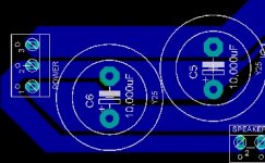
Here is (I can send it by four pieces) the PCB. The first piece is the on board stabilisators, second is the non-inverted parallel unit, third part is inverted parallel unit and the last one is buffer op-amp...
Please make some comments about my design. For example; are power lines enoughly thick for a high power amplifier? GND lines are suit for hums? Or etc...
Thanks.
Attachments
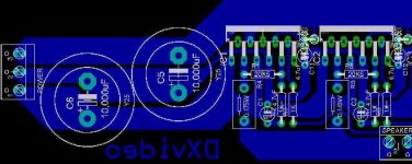
Hi, the board looks ok to me, as with the bridge mode of opperation there are no large grounde currents flowing from teh speaker -ve terminal to wory about. However, one thing which isn't clear to me is how you are going to attach the chips to a heat sink, as there is a large distance between them and the edge of your PCB.
Its a good question.. I planned it for a week... I will attach LM3886s to a "U" shape aluminium thick part and will attach it to the board and after all attach all them to the heat sink. I know its hard to realise it but I will fix the heatsink to the back of the case so all other materials will hang on it... Is it clear? (in my poor English!)
But I'm still worrying about the GND and power lines. Because in my old experience (2 x LM1876) I had a lot of 100Hz noise because of GND lines (or they said that)... So u sure that the GNS lines doesnt make a ground loop?
Thanks...
But I'm still worrying about the GND and power lines. Because in my old experience (2 x LM1876) I had a lot of 100Hz noise because of GND lines (or they said that)... So u sure that the GNS lines doesnt make a ground loop?
Thanks...
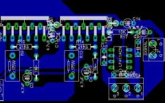
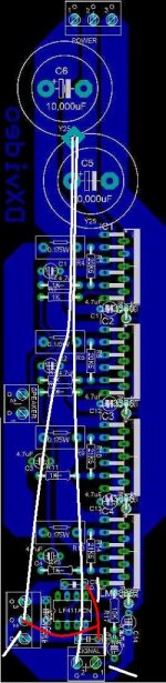
Hi, well I guess your ground lines are rather thin in places (see where I have circled below) so if there is a significant current flowing through the ground line, there will be a significant voltage created on the line, whihc my effect the zero reference point for the amp, and will generaly vary with the power supply hum (because of where trhe decoupling capacitors are connected) so you might want to try and find a way of routing the ground without any small traks. However, as this is a bridged amp, I'm not entirely sure you will still experience such problems, as both sides of the bridge will be experiencing simmilar noise, and it may be canceled out as common mode noise at the speaker output.
Attachments
From what i've gathered, there is very little current flow on the ground pin on the 3886, and i don't think its even there on the 3875? With the bridged circuit there isn't a ground return from speaker either, so ripple current from capacitors should be the only high current section.
Even still, i would make that part as circled a tad thicker, just because it does look very small, no scientific explanation")
Even still, i would make that part as circled a tad thicker, just because it does look very small, no scientific explanation
Thank you all..
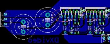
To make a star ground; Does the line between power ground and signal ground (as you can see its going under IC..) plus another line from +/-15V regulated input to power ground will enough? And will cut the line between signal ground to +/-15V regulated input ground? Do you understand? (because I cannot understand what did I write...)
Best regards...

Dxvideo said:To make a star ground; Does the line between power ground and signal ground (as you can see its going under IC..) plus another line from +/-15V regulated input to power ground will enough? And will cut the line between signal ground to +/-15V regulated input ground?
Hi,
Disconnect signal ground from chips ground (under chip) line and connect them directly to star ground. Disconnect small caps on LF411 from chips ground and connect them directly to star ground.
Power (+-15V) ground connect directly to star ground.
Regards
- Status
- This old topic is closed. If you want to reopen this topic, contact a moderator using the "Report Post" button.
- Home
- Amplifiers
- Chip Amps
- My BPA200 PCB