I won't claim to have read EVERY article on virtual grounds, but I have certainly read a lot. I have come up with a virtual ground that I am comfortable with (again, sorry, but I do not currently have acces to a scanner. I will post schematic when I can.) Anyway, the question I asked was NOT how to design a virtual ground or which design to use, but HOW/WHERE to connect it both to the chassis and to the specific chipamp.com board. On the chipamp board, there are attachment points for FOUR grounds (V+/G, V-/G, Sig In/G, Sig Out/G) all of which are joined in a large ground plane. My plan is to use ALL FOUR , using twisted pairs. Now at this point all the "grounds" are accounted for, but NOTHING is connected to the chassis or EARTH. Where/how do I do that?
Well good luck. I hope you share your circuit and how well it works.
Does point 'A' also connect to the chassis? If yes, doesn't that create a ground loop? If no, what does the ground symbol refer to?
My bad, that illustration is part of a series (hence the 5), so it doesn't give all the information all by itself. The shown method is intended specifically to prevent ground loops.
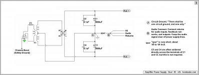
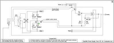
Point A is circuit ground, complying with the rule, "There shall be one circuit ground point, and one only." It does not connect to the chassis.
The "spur" is very short, perhaps 1/8 to 1/4 inch, approximately.
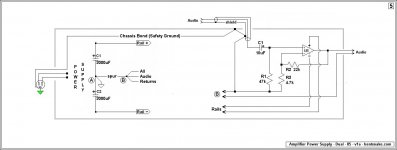
Point B is the audio common, to which all audio returns connect. It does connect to the chassis as shown, and is the bond for the circuit ground..
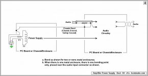
Make a distinction between grounding, which is the audio circuit, and bonding, which is the connection between the audio circuit and the rest of a building's electrical system, specifically the building's grounding system.
The small green triangle is the third prong of the power plug that goes to the wall. It's the audio circuit's single connection to the building's grounding system.
Why do we want this connection? Because...
All electrical devices having this third prong are thereby connected to the building's grounding system. In the case of audio equipment this means the chassis and cable shields of all are connected to the same grounding system (the building's), making them electrically the same point (at least in theory, and close enough in fact).
This prevents ground loops because ground loops are unwanted current flow in ground conductors. By making all ground conductors electrically the same point, current has no reason to flow (zero volts between points) and ground loops are prevented.
The chassis bond point is near the input connector because the incoming audio signal is the smallest voltage present (usually), and in any case obviously needs the most protection.
Kinda-sorta clear, I hope? These things are sometimes not easy to grasp without animated visual aids.
.
Last edited:
Now I am more confused than ever. To be sure I have the right terminology,
A= Power Supply Ground
B= Signal Ground
Green triangle = Earth Ground and chassis connection to Earth
From there, I see that B is connected to chassis at the input socket. If A is NOT connected to the chassis at all, doesn't it mean that the 'default' ground path for A has to go through B to the chassis? Not what I would think you want. I would have assumed that you would want the power supply ground to be connected to chassis (earth) and - perhaps - have the signal ground 'lifted' with a resistor/diode "loop breaker". (Note that this is not possible for me as the PCB joins Signal and Power gnds on the board.)
My knowledge is certainly rudimentary, but it is my understanding that in these things - perhaps particulaly for chipamps - you cannot ignore the resistance of the wires and assume that things connected are "electrically equal."
You can connect the ground on the underside of the board at the output ground (see Audiosector build guide) or split the ground lead into two and connect to both of the power grounds.
That was for a single channel. For two channels create a star ground between the boards, here you can connect short leads to the +/-power grounds or output grounds.
Just skip all that A and B stuff. Chipamp.com have done that for you already, its on the board.
That was for a single channel. For two channels create a star ground between the boards, here you can connect short leads to the +/-power grounds or output grounds.
Just skip all that A and B stuff. Chipamp.com have done that for you already, its on the board.
Last edited:
Agreed. Now, what about the grounded input sockets? Is that a problem? and should I do some major chassis work to get the sockets to 'float'? Or is it OK to leave them grounded? Of course, I will run twisted pairs tin Sig In/Gnd in either case.Just skip all that A and B stuff. Chipamp.com have done that for you already, its on the board.
Kinda-sorta clear, I hope?
Now I am more confused than ever.
So not. Right.
This is my fault for not respecting what you didn't know. For the benefit of future Google generations.
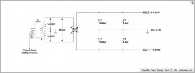
Figure 1 is simply the usual schematic for a power supply. You're supposed to look at it and admire the simplicity of the concept.
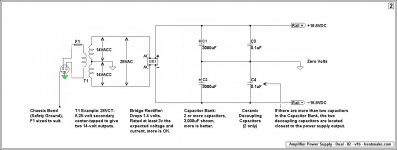
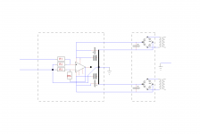
Figure 2 is the same (literally) schematic, but with notes added that I hope are self-explanatory.
Figure 3 is electrically identical to the first two, but mechanically different because real-world wiring connections are shown.
Figure 3 is where the various this-grounds and that-grounds come in. All these different "grounds" seem to--and do--violate the rule of "one ground point, and one only." I resolve this conflict by referring to everything except the shown Point A as "commons."
Figure 4 shows the chassis bond. This is also called chassis ground, safety ground, and probably a dozen other names.
Figure 5 brings everything together--I hope--showing how the audio circuit connects to the power supply.
.
Attachments
Last edited:
Perspective
.
One bonding wire, one chassis, one connection. Are we done making it complicated yet?
You're building, for crying out loud, a Cmoy. Chu Moy knocked out a li'l bog-simple circuit that's as bulletproof as such a thing can be. Jillions have been successfully built. The fact that you're building a grownup version of the thing doesn't change its basic simplicity.
Your original question that I replied to was, "...all the 'grounds' are accounted for, but NOTHING is connected to the chassis or EARTH. Where/how do I do that?" So in post #15 of this thread I posted an illustration of how the chasis bonding requirement might be dealt with.
I was answering that question, and only that question. And frankly, if you'd run the chassis bond as illustrated you'd have been long since done and happy. But no, you had to go and think.
Well, it was my li'l illustration that started all this thinking, and confused matters. So I guess it behooves me--still behooves me--to try to set matters right.
BUT be aware that your present circuit ground setup is fine. You said you had the circuit ground situation under control, and you do. This is partly because you took care, and partly because you cannot wire up a Cmoy the wrong way, because there is no wrong way. Some experts are going to want to argue about that, I hope they'll forgive me when I don't argue back.
So your circuit ground is fine, it's only the chassis bond that remains is question. So.
You're correct about resistance, but you're thinking in either-or terms, and that concept doesn't apply in electronics. Zero volts is not really zero...a 1k resistor isn't really 1k...everything in electronics is a compromise, you always have to give up some of A to get more of B. So don't think in terms of yes or no, think of getting the best possible maybe.
.
.
One bonding wire, one chassis, one connection. Are we done making it complicated yet?
You're building, for crying out loud, a Cmoy. Chu Moy knocked out a li'l bog-simple circuit that's as bulletproof as such a thing can be. Jillions have been successfully built. The fact that you're building a grownup version of the thing doesn't change its basic simplicity.
Your original question that I replied to was, "...all the 'grounds' are accounted for, but NOTHING is connected to the chassis or EARTH. Where/how do I do that?" So in post #15 of this thread I posted an illustration of how the chasis bonding requirement might be dealt with.
I was answering that question, and only that question. And frankly, if you'd run the chassis bond as illustrated you'd have been long since done and happy. But no, you had to go and think.
Well, it was my li'l illustration that started all this thinking, and confused matters. So I guess it behooves me--still behooves me--to try to set matters right.
BUT be aware that your present circuit ground setup is fine. You said you had the circuit ground situation under control, and you do. This is partly because you took care, and partly because you cannot wire up a Cmoy the wrong way, because there is no wrong way. Some experts are going to want to argue about that, I hope they'll forgive me when I don't argue back.
So your circuit ground is fine, it's only the chassis bond that remains is question. So.
My knowledge is certainly rudimentary, but it is my understanding that in these things - perhaps particulaly for chipamps - you cannot ignore the resistance of the wires and assume that things connected are "electrically equal."
You're correct about resistance, but you're thinking in either-or terms, and that concept doesn't apply in electronics. Zero volts is not really zero...a 1k resistor isn't really 1k...everything in electronics is a compromise, you always have to give up some of A to get more of B. So don't think in terms of yes or no, think of getting the best possible maybe.
.
Last edited:
Possibly a Root Cause
<< If A is NOT connected to the chassis at all, doesn't it mean that the 'default' ground path for A has to go through B to the chassis? >>
This might be a root cause of confusion. Fact: any current flow from the audio circuit to the chassis is exactly what you don't want. That is to say, if current is flowing from A (circuit ground) to the chassis, then something is broken.
The chassis bond is for shielding, and for safety. It has nothing to do with the audio circuit--or it's not supposed to.
<< perhaps...have the signal ground 'lifted' with a resistor/diode "loop breaker" >>
In my opinion ground lifts, loop breakers, and all their variations are sloppy workarounds that are dangerous (they undo the chassis bond), and probably illegal where you live.
For A and B reference I'm again posting my illustration 5 below. This illustration has been heavily revised based on your questions, so thanks for asking!
.
Now I am more confused than ever. To be sure I have the right terminology,
A= Power Supply Ground
B= Signal Ground
Green triangle = Earth Ground and chassis connection to Earth
From there, I see that B is connected to chassis at the input socket. If A is NOT connected to the chassis at all, doesn't it mean that the 'default' ground path for A has to go through B to the chassis?...
...Not what I would think you want. I would have assumed that you would want the power supply ground to be connected to chassis (earth) and - perhaps - have the signal ground 'lifted' with a resistor/diode "loop breaker". (Note that this is not possible for me as the PCB joins Signal and Power gnds on the board.)...
...My knowledge is certainly rudimentary, but it is my understanding that in these things - perhaps particulaly for chipamps - you cannot ignore the resistance of the wires and assume that things connected are "electrically equal."
<< If A is NOT connected to the chassis at all, doesn't it mean that the 'default' ground path for A has to go through B to the chassis? >>
This might be a root cause of confusion. Fact: any current flow from the audio circuit to the chassis is exactly what you don't want. That is to say, if current is flowing from A (circuit ground) to the chassis, then something is broken.
The chassis bond is for shielding, and for safety. It has nothing to do with the audio circuit--or it's not supposed to.
<< perhaps...have the signal ground 'lifted' with a resistor/diode "loop breaker" >>
In my opinion ground lifts, loop breakers, and all their variations are sloppy workarounds that are dangerous (they undo the chassis bond), and probably illegal where you live.
For A and B reference I'm again posting my illustration 5 below. This illustration has been heavily revised based on your questions, so thanks for asking!
.
Attachments
Now I am more confused than ever. To be sure I have the right terminology,
A= Power Supply Ground
B= Signal Ground
Green triangle = Earth Ground and chassis connection to Earth
From there, I see that B is connected to chassis at the input socket. If A is NOT connected to the chassis at all, doesn't it mean that the 'default' ground path for A has to go through B to the chassis?...
Does point 'A' also connect to the chassis? If yes, doesn't that create a ground loop? If no, what does the ground symbol refer to?
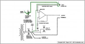
Douglas Self's by-now-infamous figure 14.1 is is not exactly self-explanatory, so I'm posting it again, this time with Mr. Self's comments. The figure and quote are from his "Audio Power Amplifier Design Handbook," pages 402 and 405.
If you're not familiar with Mr. Self, he's an audio guru of international reputation. Books, articles, lectures, the whole 9 yards. He says:
"...put the audio-chassis ground connection at the input connector, so in Figure 14.1, ground-loop currents must flow through A–B to the Protected Earth at B, and then to mains ground via B–C. They cannot flow through the audio path E–F...
...This topology is very resistant to ground-loops, even with an unbalanced input; the limitation on system performance in the presence of a ground-loop is now determined by the voltage-drop in the input cable ground, which is outside the control of the amplifier designer."
Mr. Self's point E is essentially my point A. His point F is essentially my point B.
.
Attachments
Best to insulate the input sockets from the chassis. No need to add the chassis to audio circuit.
Not insulating the input sockets may lower the overall impedance of the ground track and makes the circuit more silent than otherwise.
Douglas Self's by-now-infamous figure 14.1 is is not exactly self-explanatory, so I'm posting it again, this time with Mr. Self's comments. The figure and quote are from his "Audio Power Amplifier Design Handbook," pages 402 and 405.
If you're not familiar with Mr. Self, he's an audio guru of international reputation. Books, articles, lectures, the whole 9 yards. He says:
"...put the audio-chassis ground connection at the input connector, so in Figure 14.1, ground-loop currents must flow through A–B to the Protected Earth at B, and then to mains ground via B–C. They cannot flow through the audio path E–F...
...This topology is very resistant to ground-loops, even with an unbalanced input; the limitation on system performance in the presence of a ground-loop is now determined by the voltage-drop in the input cable ground, which is outside the control of the amplifier designer."
Mr. Self's point E is essentially my point A. His point F is essentially my point B.
.
I don't know if I am brave or foolish, but I'll take one more stab at this and then I promise to shut up.
I get the connection of the audio input "ground" (shield of RCA) to chassis, however, I have never seen a "star ground" (point F) that was not connected to chassis as well. It would seem to me that this breaks the rule "one and only one connection..." but maybe I'm just dense.
Read this thread for more thorough information on grounding,
http://www.diyaudio.com/forums/chip-amps/252436-lm3886-pcb-vs-point-point-data.html#post3845470
As well as Tomchr's site here,
LM3886 chip amp grounding.
Taming the LM3886 Chip Amplifier
http://www.diyaudio.com/forums/vend...mposite-amplifier-achieving-0-0004-thd-n.html
They are not only for the LM3886, but good grounding techniques that are explained to be applied for all amplifiers and how it works with tested results.
FWIW
jer")
http://www.diyaudio.com/forums/chip-amps/252436-lm3886-pcb-vs-point-point-data.html#post3845470
As well as Tomchr's site here,
LM3886 chip amp grounding.
Taming the LM3886 Chip Amplifier
http://www.diyaudio.com/forums/vend...mposite-amplifier-achieving-0-0004-thd-n.html
They are not only for the LM3886, but good grounding techniques that are explained to be applied for all amplifiers and how it works with tested results.
FWIW
jer
Not insulating the input sockets may lower the overall impedance of the ground track and makes the circuit more silent than otherwise.
May lower the impedance of the ground track between where?
between the inputs or between the inputs and transformer?
The primary reason for grounding the amp circuit is safety. Connecting the mains ground/earth to a virtual ground is not going to accomplish that.
I don't know if I am brave or foolish, but I'll take one more stab at this and then I promise to shut up.
I get the connection of the audio input "ground" (shield of RCA) to chassis, however, I have never seen a "star ground" (point F) that was not connected to chassis as well. It would seem to me that this breaks the rule "one and only one connection..." but maybe I'm just dense.
Maybe there's a third alternative. Maybe you just want to find some stuff out, but nobody has answered your questions yet.
<< It would seem to me that this breaks the rule... >>>
Er...maybe I should have emphasized. Any "rule" I give you is a rule of thumb, sometimes created by me, sometimes that I got from somebody else. The purpose of rules of thumb is to bypass the math and get on with it. I don't give out any rules any that I don't have confidence in. That is, personally have confidence in, for what that's worth to anybody.
<< I have never seen a "star ground" (point F) that was not connected to chassis as well. >>
Mr. Self's point F, and my point B, are essentially identical, and both are bonded to the chassis. I don't know what you mean by "as well." You speak of a star ground, as well as something else. As well as what?
It might be worth adding that "star ground" is high on anybody's list of misused terms. It's become nearly meaningless, any ol' jumble of wires might be called a star ground.
<< It would seem to me that this breaks the rule "one and only one connection..." >>
I don't know whose rule you're referring to, or what connection. Do you mean the chassis bond? Both myself and Mr. Self comply with the "one chassis bonding point" rule. This is indicated in both his circuit and mine.
After that, have you noticed how much conflicting advice you get around here? You've even been told that in this highly technical field you should follow no rules. So does it really surprise you that self-appointed experts scream you're-wrong back and forth at each other?
I counsel as follows: connect the bare--or third--wire to the chassis. Hook whatever you call ground to the chassis. It's a Cmoy, it will be fine.
Or if you want to listen to somebody, then pick an expert, any expert. Close your eyes and point. Then consult only with that person, listen only to that person. Otherwise your head will be swimming--as it is now--filled with conflicting theories. Any plan may be better than no plan, but you can't follow a dozen plans at once.
.
Last edited:
The primary reason for grounding the amp circuit is safety.
The primary reason for earthing a metal chassis powered by mains is safety.
And it seems to be the only reason to do so, it has no effect to reduce interferences of any kind. Double insulation allows to get rid of earth connection without danger.
The primary reason for grounding the amp circuit is safety.
The primary reason for earthing a metal chassis powered by mains is safety.
The primary reason for using correct terms is that everybody knows what everybody is talking about, as opposed to getting into long I-meant-you-meant discussions, and sometimes screaming matches.
Any connection made to a building's grounding system is a bonding connection, he said with a hopeless sigh. Wondering at the same time, wherefore such delight in obfuscation?
.
Last edited:
In the US they use the word ground instead of earth.
Wiki:
Grounding:
Typically a third conductor, called ground (or "safety ground") (U.S.) or protective earth (UK, Europe, IEC), is used as a protection against electric shock, and ordinarily only carries significant current when there is a circuit fault. Several different earthing systems are in use.
Is the ground/earth wire bonded in the socket, plug or to the audio circuit? Is the wire bonded to the chassis and connected to the socket/plug? Is a wire that is connecting a socket earth pin and the chassis, a connection or a bond?
I use the word "connection" to mean a bridge between two places and not to describe the way it should be fastened.
"Double insulation" or class II, The mains ground/earth is not bonded (connected) to the chassis, and the audio circuit is not bonded (connected) to the chassis.
Last edited:
- Status
- This old topic is closed. If you want to reopen this topic, contact a moderator using the "Report Post" button.
- Home
- Amplifiers
- Chip Amps
- Virtual ground in Cmoy amp