Hello I am starting to plan out a speaker design. I will hopefully have a sub, left and right midrange. And left and riggt tweeters.
Would it be better to have thr signal go to the AMP and then the filters or the other way around?
I am thinking filters then amp, because it will be hard to make the filters able to handle the high wattage.
Thank YOU
Would it be better to have thr signal go to the AMP and then the filters or the other way around?
I am thinking filters then amp, because it will be hard to make the filters able to handle the high wattage.
Thank YOU
It would be better to have the filters at line level, i.e. before the power amplifiers. Then you need an amp for each filter output, i.e. an amp for each driver that is in your speakers.
Doing it that way is often called bi-amping or tri-amping, depending on whether your speakers are two-way or three-way.
Doing it that way is often called bi-amping or tri-amping, depending on whether your speakers are two-way or three-way.
doing it that way is more often referred to as active speakers. Some countries/builders colloquially misname this as bi-amping...........Doing it that way is often called bi-amping or tri-amping, depending on whether your speakers are two-way or three-way.
Bi-amping is using two amplifiers to separately drive the quad terminals of a passive crossover two way speaker.
Well that's an interesting idea, designing each power amplifier as an active filter.
I think it might work well. But if I were doing it I think I would opt to build power amplifiers with flat frequency responses and use separate filters. That way, the amplifiers would also be able to be used as general purpose amps, and the filters could be modified without modifying the power amplifiers. And the design process should be simpler. Op amps and the other components needed for the filters will be extremely cheap, anyway. However, they will need a small bi-polar power supply, like + and - 15Volts at up to at least a couple hundred mA, if they are not passive filters.
There is (or at least there used to be) software called filterpro that was a free download from ti.com . It designs active opamp-based filters for you, up to sixth-order.
You can (and should) read a lot more about the different types of filters, in two or three of the chapters in this book (also a free download): ADI - Analog Dialogue | Op Amp Applications Handbook .
For the power amps, eventually you should probably look at the power amp version of "The Wire", which uses LME49830 chips with lateral mosfets as the output devices. I believe that there are now PCBs available, again, too! Or, you could instead use a "plain" chipamp, such as the LM3886, or one of the TDA models, or something else
You could even just use something like three used ready-made power amplifiers, from eBay, such as the Adcom GFA-535/545/555 series, or a Hafler DH-220. You could probably get three of them for about $300 if you were careful and patient. They are built like tanks and worth the money for the case, heatsinks, and power supplies, alone! But wait, you probably don't need 100 Watts or more per driver. So you could use smaller, less costly amps than those models (although the Adcom GFA-535 might be perfect for something, at 60 Watts per channel into 8 Ohms and able to drive 4 Ohms with about 100 W per channel with no problem at all).
Last edited:
So I have come up with a simple design to start off with.
I want to have a output range from less then a Watt to about 80 Watts
I read that since sub woofers are less responsive I should give it twice the power as the tweeters, and mid range; Is this true?
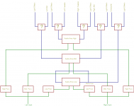
I will attach a block diagram that I made illustrating my idea.
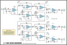
Right now I am thinking of following the crossover schematic that has been attached. Would this be a good choice?
For my amps, I think I will use 3 LM4072- I will attach the datasheet. Would this be a good choice.
I have a few more Qs:
1. Since I only want one sub-woofer can I just connect the right and left inputs to get mono audio?
2. For my light effects can I just use a Transistor?
3. Would it be unwise to build all of this on a perfboard?- I have already tried my hand at PCB making, and the results were inferior.
Any advice at all is greatly appreciated.
I want to have a output range from less then a Watt to about 80 Watts
I read that since sub woofers are less responsive I should give it twice the power as the tweeters, and mid range; Is this true?
I will attach a block diagram that I made illustrating my idea.
Right now I am thinking of following the crossover schematic that has been attached. Would this be a good choice?
For my amps, I think I will use 3 LM4072- I will attach the datasheet. Would this be a good choice.
I have a few more Qs:
1. Since I only want one sub-woofer can I just connect the right and left inputs to get mono audio?
2. For my light effects can I just use a Transistor?
3. Would it be unwise to build all of this on a perfboard?- I have already tried my hand at PCB making, and the results were inferior.
Any advice at all is greatly appreciated.
Attachments
First, I completely second what Gootee suggested at post #6
Next,
1. Apex has a sub-woofer driver circuit in his thread in analogue section, if I am not mistaken. That nicely mixes stereo signal to mono to drive a single sub woofer I guess.
2. I made a stereo LED bar graph display using a perf-board long ago with transistor. It was a simple circuit and can be easily made in perf-board. But 2 X LM3915 is also a great option.
Regarding your question 3:
I made a circuit like this and using it in my 3 way active speaker setup with 6 tda2050 chips. Details in this thread:
http://www.diyaudio.com/forums/anal...tive-crossover-christmas-holiday-project.html
This is a magical circuit. It makes even crappy speakers sound brilliant in my case. I am truly happy with it's performance and will build another soon for my parents.
Imho, this circuit ( from siliconchip.com, I guess) can be assembled on a perf-board if the soldering skill is extremely well and you have a great dual regulated PSU.
But it can be confusing at times and error prone and more, it can be hard to trouble shoot in future with perf-board. The best option to make a PCB. I saw two more people made this PCB here.
There is an excellent PCB making tutorial at construyasuvideorockola.com ( a Spanish site ) which boosted my DIY PCB making skill further. I learned many cool tips from that great site.
All the very best")
Next,
1. Apex has a sub-woofer driver circuit in his thread in analogue section, if I am not mistaken. That nicely mixes stereo signal to mono to drive a single sub woofer I guess.
2. I made a stereo LED bar graph display using a perf-board long ago with transistor. It was a simple circuit and can be easily made in perf-board. But 2 X LM3915 is also a great option.
Regarding your question 3:
I made a circuit like this and using it in my 3 way active speaker setup with 6 tda2050 chips. Details in this thread:
http://www.diyaudio.com/forums/anal...tive-crossover-christmas-holiday-project.html
This is a magical circuit. It makes even crappy speakers sound brilliant in my case. I am truly happy with it's performance and will build another soon for my parents.
Imho, this circuit ( from siliconchip.com, I guess) can be assembled on a perf-board if the soldering skill is extremely well and you have a great dual regulated PSU.
But it can be confusing at times and error prone and more, it can be hard to trouble shoot in future with perf-board. The best option to make a PCB. I saw two more people made this PCB here.
There is an excellent PCB making tutorial at construyasuvideorockola.com ( a Spanish site ) which boosted my DIY PCB making skill further. I learned many cool tips from that great site.
All the very best
Last edited:
IMO, power is used more efficiently when you get rid of the passive crossovers and use separate amps, so huge power to each driver isn't usually necessary. It seems like an actively crossed system multi-amp with a total of 100 watts will play louder and cleaner than a passively crossed single amp 100 watt system. I've heard that more power is needed for the woofers but it depends entirely on the speaker design and type of music you play. I put my largest amp on the midrange/midbass drivers because they were inefficient and things like vocals can require more than the bass. The beauty of a passively crossed system is that you have infinite ability to mix, match and tweak.
Last edited:
OK. That looks OK so far.
You will have to decide how to package everything. For example, will you build three stereo amplifiers in three boxes, or will you build two boxes, one per channel, with three power amplifiers in each box, or will you build one box with six amplifiers? In each case, you also get to decide how many separate power transformers to use.
You will probably want to do one thing at a time so I would leave the lighting effects for last.
The maximum output power for each frequency range will probably vary. As you noted, the bass will need more power than the mid and treble. And the mid might need more power than the treble. You will have to do some research to find out what reasonable maximum output power is for each range.
For 80 Watts RMS out, the peak output voltage and current can be calculated knowing only the load impedance. Typically we could assume 8 Ohms or 4 Ohms. It is possible to make your power amplifiers and power supplies capable of both.
Let's see if I can re-derive the equations:
Power_rms = P_rms= Vrms²/Rload
Vrms² = (P_rms ) (Rload)
Vrms = Vpk/(√2)
(Vpk/(√2))² = (P_rms)(Rload)
Vpk²/2 = (P_rms)(Rload)
Vpk = √(2(P_rms)(Rload))
So for 80 Watts RMS into 8 Ohms:
Vpk = √(2(80)(8)) = 35.8 Volts
Ipk = Vpk / Rload = 4.48 Amps.
In order to calculate the needed transformer output voltage, you would add (to Vpk) the voltage across the output stage (guess about 5V), plus the peak-to-peak ripple voltage (say 5% of Vpk), plus the rectifier diode drops (guess 2V), plus at least 10% in case the AC line voltage is lower than typical. If you wanted it to be regulated, you would also need to add somewhat more than the worst-case regulator drop-out voltage. And since transformer output voltages are rated as RMS voltages, you also need to convert the peak to RMS.
Vxfmr_pk_out(Vpk) = Vpk + Vamp + Vripple_p-p + Vdiodes + Vpct_sag
Vxfmr_pk_out(Vpk) = Vpk + 5v + (0.05)Vpk + 2v + (0.10)Vpk
For 80 Watts RMS into an 8 Ohm load:
Vxfmr_pk_out(35.8) = 35.8 + 5v + (0.05)35.8 + 2v + (0.10)35.8 = 48.2 Volts
Vxfmr_rms_out = Vxfmr_pk_out / (√2) = 34 Volts RMS secondaries.
That would be the minimum transformer secondary voltage, for each power rail, in order to ensure that there would be enough headroom for the signal, while operating at the maximum output power level, ASSUMING that all of he many assumptions hold, and with 8 Ohms load.
You would need to calculate the minimum reservoir capacitance that would guarantee the p-p ripple voltage was always less than the specified value, in this case 0.05 x 35.8 = 1.8 Volts. For 80 Watts into 8 Ohms, I would use about 22000 uF per rail, rated at 63V or so. I would probably just use five 4700 uF caps in parallel, per rail. You should move one of them as close as possible to the amplifier's power supply input pins.
P.S. No guarantee that my math or arithmetic is correct. Better check it when you do the calculations.
Last edited:
Yeah, I didn't explain that, the first time, actually.
I derived it in the thread entitled "Power Supply Reservoir Size", which was started by Nico Ras.
Knowing the maximum load current and the desired maximum peak-to-peak ripple amplitude, the minimum required reservoir capacitance can be calculated.
Since for an ideal capacitor, i = C dv/dt, we can make some assumptions and linearize in a neighborhood and say (ignoring ESR):
C = i Δt / Δv
where Δv is the desired maximum dip in the supply rail voltage when i amps are drawn for Δt seconds, and C is in Farads.
We can assume that Δt can, at worst, be the time between charging pulses, i.e. 1 / (2 fmains). And we get to pick Δv, the p-p ripple amplitude. And we can calculate the maximum load current.
Most people use the RMS current. But that isn't really good enough, because it only accounts for the possibility of a single sine wave and we should try to account for the worst case load. And that would be a DC voltage and current at the Vpk and Ipk level.
The Δv should be chosen carefully, taking into account the specified Vpk and the Vclip of the amplifier itself, to leave room for the Vripple, relative to the peak rail voltage. So
Δv = Vrail - Vclip - Vpk
I've done the algebra, and also took into account the ESR, using the approximation
ESR = 0.02 / ( C x Voltage_Rating)
and the overall equation for the minimum value of the required capacitance is
Cmin (in uF) = 1000000(Vpk/(Rload(Vrail-Vclip-Vpk)))( (1/(2 fmains)) + (0.02/Voltage_Rating) )
I just guesstimated the 22000 uF, from a spreadsheet I looked at that uses that equation. But we should check to see what the equation gives, for the 80 Watt into 8 Ohms case (assuming 60 Hz fmains):
Cmin = 1000(35.8/(8(46.2-5-35.8))) ((1/120)+(0.02/63))
Cmin = 7169 uF
That agrees with my spreadsheet, too, but it also results in over 5 Volts p-p ripple.
If we want ripple around 1.9 Volts, we get 22000 uF (and the max power without clipping also rises to about 96 Watts, with Vpk a little over 39 Volts).
BUT NOTE that if you use a 10% lower rail voltage, then 21800 uF would give you 1.73 V ripple and only 76 Watts RMS max, at the onset of clipping.
So that's why I picked 22000 uF.
You can find my Excel spreadsheet and download it from the thread I mentioned. Sorry I don't have the exact link at hand right now.
Last edited:
Links to my Power Supply solver and minimum reservoir capacitance Excel spreadsheets are in the post at:
http://www.diyaudio.com/forums/soli...n-attempt-number-2-simpler-9.html#post3532280
http://www.diyaudio.com/forums/soli...n-attempt-number-2-simpler-9.html#post3532280
THANK YOU
Alright, Today I thought I would start to design my enclosures, but I am having a lot of trouble. I've tried various software and online calculators, but all of them have many differant paramateres for the speaker that I do not know.
I have:
1 10" MTX sub, 8 Ohm, 125RMS
2 4.75" (12cm), Panasonic, 6 Ohm, 45RMS
2 2.375' (6cm), Panasonic, 6 Ohm, 45RMS (a "supertwetter" piezoelement is attached to this tweeter which I hope to use"
How would I go about beginning to design this?
I am thinking of a ported enclosure for the sub.
I would like indidvidual boxes for each speaker.
- Status
- This old topic is closed. If you want to reopen this topic, contact a moderator using the "Report Post" button.
- Home
- Amplifiers
- Chip Amps
- Question regarding Amp and bandpass filters.