Go and check where the wires are connected in the original amplifier.
I know ( not from experience ) that B&O are very well and HARD engineered, so it might be difficult to isolate the amplifier circuitation from the others.
You just have to follow from the Emitter ( or Collector ?? ) of the power transistors which is attached directly to the power supply ( capacitor ).
As power transistors do 'swallow' much more current than small signal ones....
Trying to sum up again.
I will be using the blue-black-blue CT secondary at 19 VAC for the stereo project, and just leave the grey-grey for no use.
most likely
")
(if there is 19V between Black and each of the blue)
Thanks. One of the first answers that said something specific i could figure out
The transformer secondaries was directly connected to the pcbs. Nothing i can follow.Go and check where the wires are connected in the original amplifier.
I know ( not from experience ) that B&O are very well and HARD engineered, so it might be difficult to isolate the amplifier circuitation from the others.
You just have to follow from the Emitter ( or Collector ?? ) of the power transistors which is attached directly to the power supply ( capacitor ).
As power transistors do 'swallow' much more current than small signal ones....
Dear troelsg: some of this discussion has wandered one way or another because we still lack some pieces of evidence.
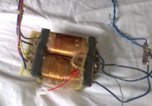
You show 2 pictures: 1 of a transformer, with coloured wires and no voltage information; another of a black and white schematic, with voltages indicated but no mention of colours.
We may *assume* which is which, but may be wrong, and it's dangerous because we are talking line voltage.
To boot, the line side is multi-tapped so it is International, and, much worse, the transformer shown and the schematic do *not* match .
Let's start with the line side:
the transformer shows 5 wires on the left, top to bottom: brown/black/yellow/red/blue
the schematic shows on the right side 2 secondaries, one of them tapped, or 5 wires in total.
Please edit the schematic drawing and label each wire with the corresponding colour.
And show how you are connecting it to the power line.
Ths schematic shows a multi voltage selector which I guess you are *not* using, please show how yu are connecting that transformer.
Now to the secondaries (right on the picture, left on the schematic):
here we are in trouble because they do not match !!!
The schematic shows one main secondary (2 wires, no center tap) which feeds a main, approx. 50 volts *single* supply (using a 4 diode bridge ¿ HBO C2200 ? and a main capacitor ¿ 3000uF 60V ? ), the schematic is quite unreadable but it clearly shows a single supply power amplifier with an output capacitor, that's why I suggested that configuration for your amplifier.
It also shows 2 110V secondaries, wired in parallel, and exiting through 2 wires, so in total we should have 4 secondary wires ... but the picture shows * 5 * ¿¿??
The picture also shows an apparent center tap (¿black?), you claim to having read 37 V from the thin grey wires, lots of differences.
There also seem to be some unused terminals on the secondary side.
I don't know whether they are connected to something (the mysterious 110V windings?) or not , they were simply there on the terminal strip.
So *please* post a hand drawing like I said, showing clearly what is connected to what, with colours and voltages.
Otherwise it may be dangerous.
As of:
The ones which go to the main bridge rectifier which then feeds the main filter cap, are the "power" wires you should use.
I guess they are the thick blue ones on the right, but guessing without measuring does not carry you very far in Electronics.
As of
PD: it looks like you have a center tap at the transformer secondary (black wire?), which is *not* shown in the schematic; if so, cool .
I *guess* the transformer and the schematic do not match, maybe they correspond to different versions of that amplifier, which might have remained in production for many years.
You show 2 pictures: 1 of a transformer, with coloured wires and no voltage information; another of a black and white schematic, with voltages indicated but no mention of colours.
We may *assume* which is which, but may be wrong, and it's dangerous because we are talking line voltage.
To boot, the line side is multi-tapped so it is International, and, much worse, the transformer shown and the schematic do *not* match .
Let's start with the line side:
the transformer shows 5 wires on the left, top to bottom: brown/black/yellow/red/blue
the schematic shows on the right side 2 secondaries, one of them tapped, or 5 wires in total.
Please edit the schematic drawing and label each wire with the corresponding colour.
And show how you are connecting it to the power line.
Ths schematic shows a multi voltage selector which I guess you are *not* using, please show how yu are connecting that transformer.
Now to the secondaries (right on the picture, left on the schematic):
here we are in trouble because they do not match !!!
The schematic shows one main secondary (2 wires, no center tap) which feeds a main, approx. 50 volts *single* supply (using a 4 diode bridge ¿ HBO C2200 ? and a main capacitor ¿ 3000uF 60V ? ), the schematic is quite unreadable but it clearly shows a single supply power amplifier with an output capacitor, that's why I suggested that configuration for your amplifier.
It also shows 2 110V secondaries, wired in parallel, and exiting through 2 wires, so in total we should have 4 secondary wires ... but the picture shows * 5 * ¿¿??
The picture also shows an apparent center tap (¿black?), you claim to having read 37 V from the thin grey wires, lots of differences.
There also seem to be some unused terminals on the secondary side.
I don't know whether they are connected to something (the mysterious 110V windings?) or not , they were simply there on the terminal strip.
So *please* post a hand drawing like I said, showing clearly what is connected to what, with colours and voltages.
Otherwise it may be dangerous.
As of:
What picowall asks is to follow the tracks *at the PCB itself* to see where those wires go.The transformer secondaries was directly connected to the pcbs. Nothing i can follow.
The ones which go to the main bridge rectifier which then feeds the main filter cap, are the "power" wires you should use.
I guess they are the thick blue ones on the right, but guessing without measuring does not carry you very far in Electronics.
As of
start by assuming, but then confirm by measuring.No, but what can i do about that, other than assuming?
PD: it looks like you have a center tap at the transformer secondary (black wire?), which is *not* shown in the schematic; if so, cool .
I *guess* the transformer and the schematic do not match, maybe they correspond to different versions of that amplifier, which might have remained in production for many years.
Sorry for the misunderstanding. All of the primary wiring is already determent. I asked this question in another tread and concluded the following:Dear troelsg: some of this discussion has wandered one way or another because we still lack some pieces of evidence.
You show 2 pictures: 1 of a transformer, with coloured wires and no voltage information; another of a black and white schematic, with voltages indicated but no mention of colours.
We may *assume* which is which, but may be wrong, and it's dangerous because we are talking line voltage.
To boot, the line side is multi-tapped so it is International, and, much worse, the transformer shown and the schematic do *not* match .
Let's start with the line side:
the transformer shows 5 wires on the left, top to bottom: brown/black/yellow/red/blue
the schematic shows on the right side 2 secondaries, one of them tapped, or 5 wires in total.
Please edit the schematic drawing and label each wire with the corresponding colour.
And show how you are connecting it to the power line.
Ths schematic shows a multi voltage selector which I guess you are *not* using, please show how yu are connecting that transformer.
Now to the secondaries (right on the picture, left on the schematic):
here we are in trouble because they do not match !!!
The schematic shows one main secondary (2 wires, no center tap) which feeds a main, approx. 50 volts *single* supply (using a 4 diode bridge ¿ HBO C2200 ? and a main capacitor ¿ 3000uF 60V ? ), the schematic is quite unreadable but it clearly shows a single supply power amplifier with an output capacitor, that's why I suggested that configuration for your amplifier.
It also shows 2 110V secondaries, wired in parallel, and exiting through 2 wires, so in total we should have 4 secondary wires ... but the picture shows * 5 * ¿¿??
The picture also shows an apparent center tap (¿black?), you claim to having read 37 V from the thin grey wires, lots of differences.
There also seem to be some unused terminals on the secondary side.
I don't know whether they are connected to something (the mysterious 110V windings?) or not , they were simply there on the terminal strip.
So *please* post a hand drawing like I said, showing clearly what is connected to what, with colours and voltages.
Otherwise it may be dangerous.
As of:
What picowall asks is to follow the tracks *at the PCB itself* to see where those wires go.
The ones which go to the main bridge rectifier which then feeds the main filter cap, are the "power" wires you should use.
I guess they are the thick blue ones on the right, but guessing without measuring does not carry you very far in Electronics.
As of
start by assuming, but then confirm by measuring.
PD: it looks like you have a center tap at the transformer secondary (black wire?), which is *not* shown in the schematic; if so, cool .
I *guess* the transformer and the schematic do not match, maybe they correspond to different versions of that amplifier, which might have remained in production for many years.
"I tried the following settings. All output meassured on the black-blue.
240: Black-Blue connected/Current on Yellow-Red: Ratio: 13.222
220: Black-Blue connected/Current on Brown-Red: Ratio: 11.55
110: Current on Blue-Red. Ratio: 5.89
130: Current on Black-Yellow. Ratio: 6.91
Could this be the connections for the four inputs. I think it makes sense. It would create an output at:
110: 18.67V
130: 18.81V
220: 18.86V
240: 18.15V"
So i found the correct connections. My concern, when making this thread was the following:
Which of the two outputs should i use for a stereo amp configuration. The CT (Blue-Black-Blue) or the single secondary (Grey-Grey).
My other concern was how to determine the VA value.
I found the diagram online, and most likely it is from another model type. Nothing i can do about that, than ignoring it as useless.
I am very new to this, so i might be a little slow. I know the voltage outputs of the grey-grey (37) and blue-black (18.5). I have an estimated VA value at around 120. What is it that is should know more about??
The unused terminals on the right was never connected for anything, and i cant figure anything out by measuring.
The grey-grey and blue-blue was both attached as pairs at the pcb. The black was attached somewhere else. I will try to get the correct diagram from B&O.
Thanks
Do you really need to know the amperage? Chip Amps are supposedly much more efficient than the regular AB amps, why not just hook it and see?No, but what can i do about that, other than assuming?
I have just purchased a pair of TDA7294 boards and screwed them to a piece of heatsink, added a power supply I knocked together from a 28 0 28 transformer taken from an old stereo. The amps works perfectly on numerous cheap to valuable speakers.
I do not know how the calculate size of heatsink or measure transformer current, just do it.
Fine.
Here we are all trying to help in good faith.
Continuing with tinitus' assumption, "logic" says that the thick wires (if they are original) are for high current, and the thinner ones for low current.
So blue/black/blue "should" be 19+19VAC (I'm rounding values) and the white/white may be anything.
Did you measure 37VAC?
Fine, anyway we won't use it.
To confirm this, measure the resistance blue/blue and white white.
Since these are very low values, you must substract the multimeter internal resistance, so first set it to the lowest scale (200 ohms) and short the black and red tips together.
It will not be "0" but a low value, usually around 0.3 or 0.5 ohms .
Remember it.
Say it's 0.5 ohms.
Then measure blue/blue , say your multimeter shows 0.8 ohms, substract the "error" 0.5 ohms and you'll find the real value: 0.3 ohms
Do the same with white/white , I expect a couple ohms .
The exact value is not important (for this test), we want to distinguish between fat and thin winding and now we can.
If you have a center tapped 19+19V AC transformer, perfect, you can build a split supply kit.
And if the kit demands dual secondaries and dual rectifier bridges, I'll tell you how to solve that.
Thanks again, and this is the data i have. All wires are orignalFine.
Here we are all trying to help in good faith.
Continuing with tinitus' assumption, "logic" says that the thick wires (if they are original) are for high current, and the thinner ones for low current.
So blue/black/blue "should" be 19+19VAC (I'm rounding values) and the white/white may be anything.
Did you measure 37VAC?
Fine, anyway we won't use it.
To confirm this, measure the resistance blue/blue and white white.
Since these are very low values, you must substract the multimeter internal resistance, so first set it to the lowest scale (200 ohms) and short the black and red tips together.
It will not be "0" but a low value, usually around 0.3 or 0.5 ohms .
Remember it.
Say it's 0.5 ohms.
Then measure blue/blue , say your multimeter shows 0.8 ohms, substract the "error" 0.5 ohms and you'll find the real value: 0.3 ohms
Do the same with white/white , I expect a couple ohms .
The exact value is not important (for this test), we want to distinguish between fat and thin winding and now we can.
If you have a center tapped 19+19V AC transformer, perfect, you can build a split supply kit.
And if the kit demands dual secondaries and dual rectifier bridges, I'll tell you how to solve that.
Meassurements.
Secondary side:
Grey-Grey: 2.0 (200) ohm
Black-Blue: 00.3
The resistance between the red and black tip: 0.00-0.01
Pretty spot on, i must give you that
Thanks again
- Status
- This old topic is closed. If you want to reopen this topic, contact a moderator using the "Report Post" button.
- Home
- Amplifiers
- Chip Amps
- Power supply for chip amp ?