Hi all,
I'm currently building a preamp. The schematic is based on something I've found in an old dusty electronics book in the local library")
It uses a LM1036N for vol/bass/treb/bal control and a TDA7050 as a headphone amplifier.
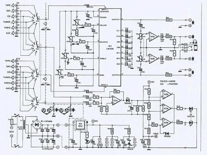
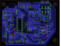
Based on the schematic I have made a PCB with Eagle. Inputs are selected on another pcb and Vsupply (12V and 5V) is also provided by another pcb using 7812 and 7805 regulators. The audio input signals will be connected via solder pens and shielded audio cable.
I've made a DIY amplifier a little while ago with PCB kits, and I've also made already some PCB's (not audio). However, this is the first time I've made an audio PCB and I'm not very sure if the ground plane I've drawn is good enough to avoid hum or noise. I've already read some stuff concerning ground loops.
Could any of you please take a look at the board to see if I haven't made any mistake or screwed some things up ?
Thx
I'm currently building a preamp. The schematic is based on something I've found in an old dusty electronics book in the local library
It uses a LM1036N for vol/bass/treb/bal control and a TDA7050 as a headphone amplifier.
Based on the schematic I have made a PCB with Eagle. Inputs are selected on another pcb and Vsupply (12V and 5V) is also provided by another pcb using 7812 and 7805 regulators. The audio input signals will be connected via solder pens and shielded audio cable.
I've made a DIY amplifier a little while ago with PCB kits, and I've also made already some PCB's (not audio). However, this is the first time I've made an audio PCB and I'm not very sure if the ground plane I've drawn is good enough to avoid hum or noise. I've already read some stuff concerning ground loops.
Could any of you please take a look at the board to see if I haven't made any mistake or screwed some things up ?
Thx
My tuppence worth:
TDA7050: voltage gain = 27dB according to datasheet. From the headphone amps I've made, I've found such gains to be excessive from line level inputs. Typically I use 6dB and thats it! You do not need much to deafen yoursef even with high-impedance types! Attenuate the input to the headphone stage. Use low value resistors no more than a couple of K-ohms to keep noise to a minimum.
LM1036: Signal level handling - dependant on what you use, this device's max input of 1.6Vrms is a liitle on the low side. Most modern CD players will give out max signal = 2.2V rms. The older (?) LM1035 seems to have higher supply rail capability of 18VDC operating and as such comfortably
takes 3V rms input.
Hi blu_glo, thanks for your reply and your advice !
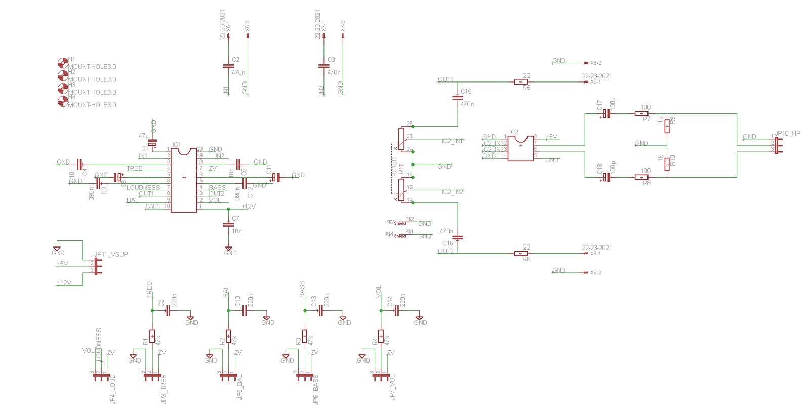
I've put an attenuator before the potmeter. This should attenuate with -20 dB (please correct me if I'm wrong !)
Apparently I've also made a little mistake with the potmeter, the connections of the left and right channel were reversed
Here is a new improved schematic:
Considering the signal level handling on the LM1036, would it be a good idea to also put an attenuator before the audio input of the LM1036 ?
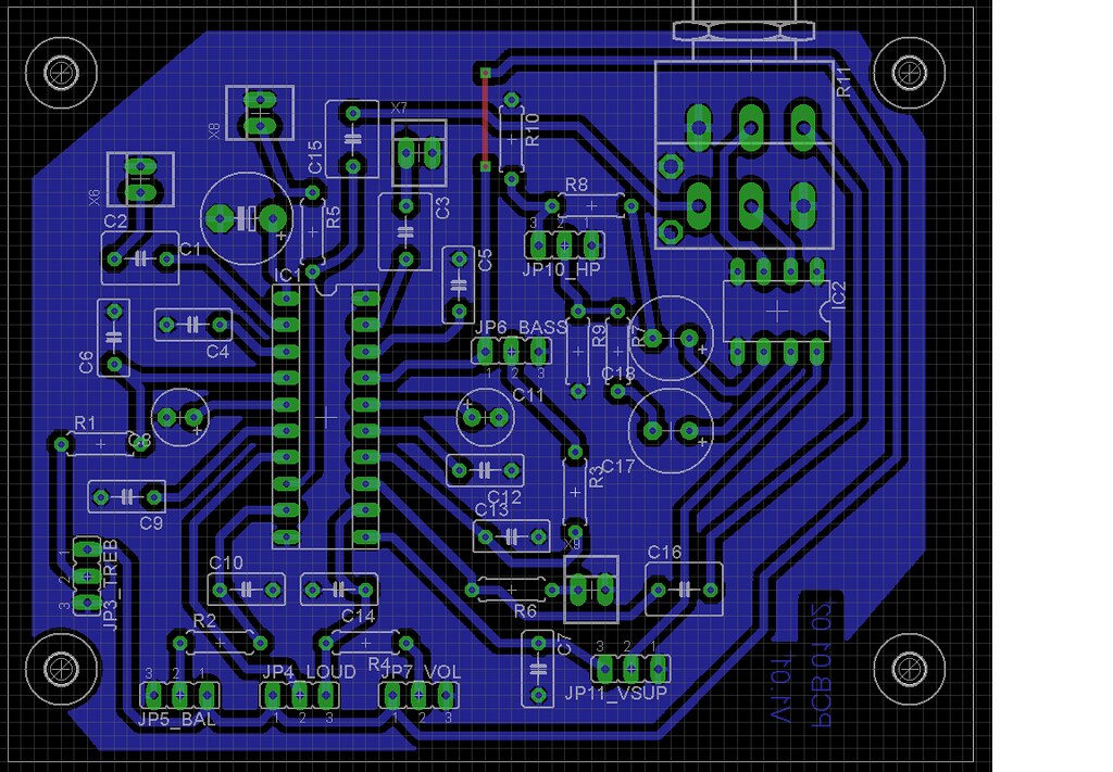
Another concern I have is the ground plane. I haven't used a star in the grounding because that would have made the routing a lot more difficult. Is it a good idea to use a ground plane the way I did on a preamp PCB ?
Greetings
Cedric
EDIT: adjustment link to image
I've put an attenuator before the potmeter. This should attenuate with -20 dB (please correct me if I'm wrong !)
Apparently I've also made a little mistake with the potmeter, the connections of the left and right channel were reversed
Here is a new improved schematic:
An externally hosted image should be here but it was not working when we last tested it.
Considering the signal level handling on the LM1036, would it be a good idea to also put an attenuator before the audio input of the LM1036 ?
Another concern I have is the ground plane. I haven't used a star in the grounding because that would have made the routing a lot more difficult. Is it a good idea to use a ground plane the way I did on a preamp PCB ?
Greetings
Cedric
EDIT: adjustment link to image
Last edited:
Your 20dB attenuator is about right, leaving you with 7dB of max headphone gain. This means you should at least be able to turn the headphone volume to a sensible position before deafening yourself!
LM1035/36 are interchangeable get your circuit running with the 1036 if you alread have it; then search out a 1035.... I wouldn't bother with the LM103x-attenuator complication, you'll loose signal/noise ratio (noise may get audibly worse)
http://www.datasheetcatalog.com/datasheets_pdf/L/M/1/0/LM1035.shtml
Ground, hereafter referred to as 0V on line preamps is not quite as critical as you may be led to believe.
Input sockets->PCB input 0V [signal wire]
PCB output 0V-> supply 0V [supply wire]
PCB output 0V->ouput RCA 0Vs [signal wire]
Do not worry about using common 0V for left and right; channel seperation is already compromised within the IC and you won't hear the difference anyway.
Connect 0V supply to metal chassis somehere near input with 22-100R resistor and 0.1uF capacitor in parallel both component values non critical!
I'm assuming by "preamp" you do mean such and the power amps are in seperate enclosures elsewhere?
Last edited:
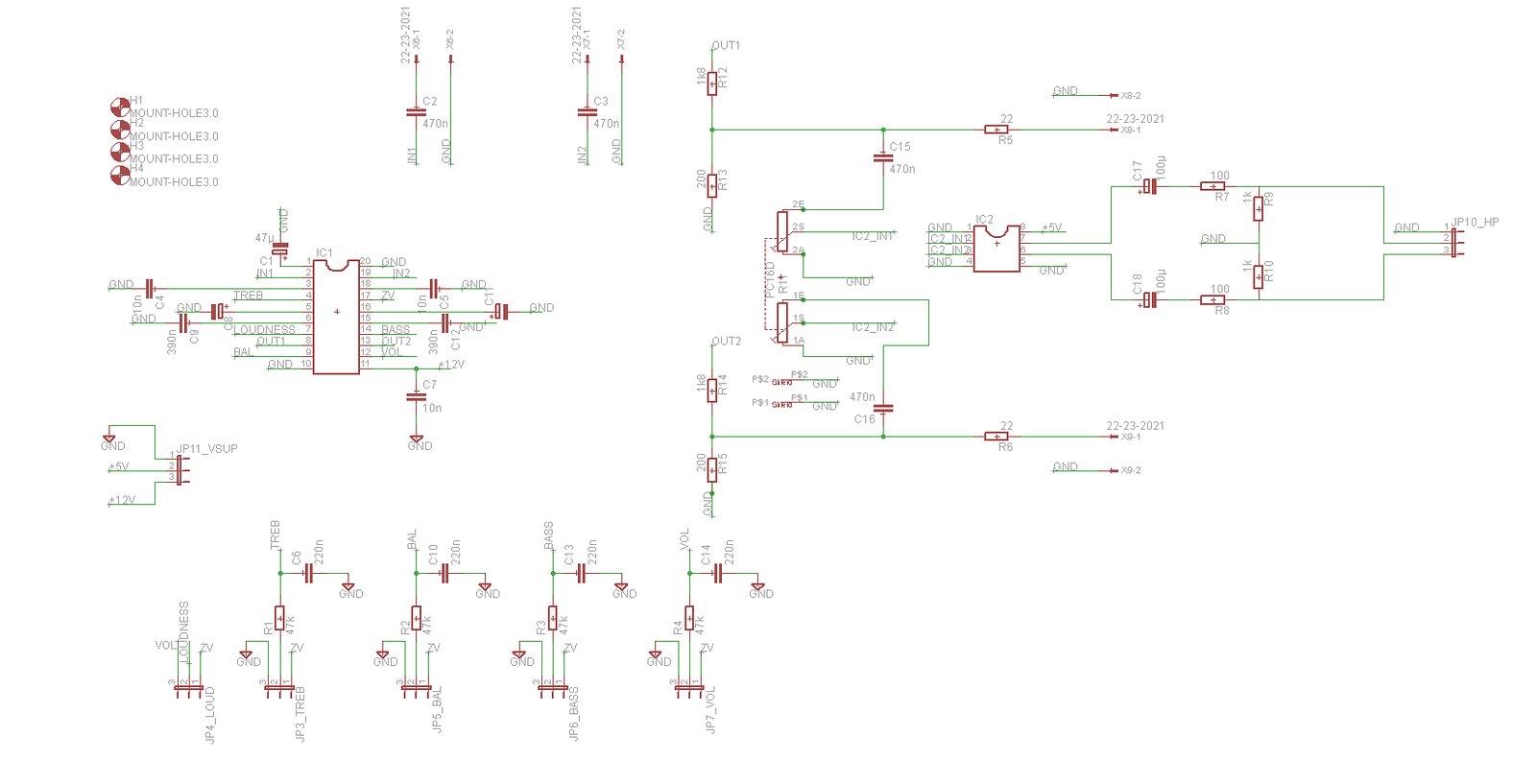
I've made a redesign of my pcb with your comments in mind. Inputs and outputs are now grouped. Output 0V is also close to power supply 0V.
This pcb will be in a separate metal enclosure. Power amplifiers will indeed be in a different metal housing. I will draw the power amps later, these will probably be based on LM3886's.
Concerning the LM1035, I've searched on Farnell, RS Components, Digikey and a couple smaller webstores but I haven't found anything ! Could it be that this LM1035 is out of production ?
Already thanks for your help !
Attachments
Could it be that this LM1035 is out of production ?
I beleive it has long since been discintinued however NOS may still be available....
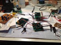
Allright, so I etched and tested the pcb. At first everything seemed ok, I've tested it with a small power amp board I once bought as a kit (with TDA2050) and the sound is good.
However if I connect a headphone to it I've got a constant "hissss". This "hisss" sound is constant (doesn't change with volume higher). I can hear and manipulate the input sound with the volume pots but the "hisss" remains
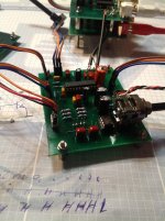
Test setup can be seen in attachments.
Anybody got any recommendations what can cause this "hissing" sound ?
Regards
Cedric
However if I connect a headphone to it I've got a constant "hissss". This "hisss" sound is constant (doesn't change with volume higher). I can hear and manipulate the input sound with the volume pots but the "hisss" remains
Test setup can be seen in attachments.
Anybody got any recommendations what can cause this "hissing" sound ?
Regards
Cedric
Attachments
It's most likely the high gain of the headphone amp IC.
Quick questions (on my way to work!)
other than the hiss is the headphone circuit working?
is it quiet hiss in the background?
what position on the volume is loud but comfortable listening?
Is the outside of the POT earthed?
have you tried an earthed metal plate underneath the PCB?
Quick questions (on my way to work!)
other than the hiss is the headphone circuit working?
is it quiet hiss in the background?
what position on the volume is loud but comfortable listening?
Is the outside of the POT earthed?
have you tried an earthed metal plate underneath the PCB?
Last edited:
other than the hiss is the headphone circuit working?
is it quiet hiss in the background?
what position on the volume is loud but comfortable listening?
Greetings
Cedric
Yes, the circuit works as it should
Yep, the hiss remains constant whatever the position of the pot
I can open the pot completely without hearing distortion or ruining my ears (sound is not too loud I mean with that)
Is the outside of the POT earthed?)
The outside of the pot is connected with the ground plane of the pcb. You can see this at the pic of the PCB I've posted earlier. However, my pcb is NOT connected to the ground in the test setup.
have you tried an earthed metal plate underneath the PCB?
No, I haven't. Could you explain this a bit more ? Is the earthed metal plate for shielding ?
Again, thanks for your help and quick reply
Greetings
Cedric
other than the hiss is the headphone circuit working?
Yes, the circuit works as it should
Good. So fundamentally it's working!
is it quiet hiss in the background?
Yep, the hiss remains constant whatever the position of the pot
So that's going to be noise from the TDA7050 which is a high gain chip. Not necessarily the best option for a headphone amplifier.....
what position on the volume is loud but comfortable listening?
I can open the pot completely without hearing distortion or ruining my ears (sound is not too loud I mean with thatIs the outside of the POT earthed?
Don't forget the LM1035 volume will also affect the signal and possibly noise passed on to this chip! try with LM1035 VOL pot set to max, then halfway and note differences (if any).
The outside of the pot is connected with the ground plane of the pcb. You can see this at the pic of the PCB I've posted earlier. However, my pcb is NOT connected to the ground in the test setup.have you tried an earthed metal plate underneath the PCB?
OK. What value is the POT? Couldn't see it in your schematic. I might suggest 10K and not much more. Also a 100pF from each chip input to earth.
No, I haven't. Could you explain this a bit more ? Is the earthed metal plate for shielding ?Again, thanks for your help and quick reply
Yes, shielding does help a lot especially where high gains are involved.
Not a problem glad to be of assistance.
Greetings
Cedric
Last edited:
Me: - OK. What value is the POT? Couldn't see it in your schematic. I might suggest 10K and not much more. Also a 100pF from each chip input to earth.
Sorry picked it out of the original, I assume you left it 22K which is not bad at all.... use ~100pf caps as previously mentioned on input pins.....
Sorry picked it out of the original, I assume you left it 22K which is not bad at all.... use ~100pf caps as previously mentioned on input pins.....
- Status
- This old topic is closed. If you want to reopen this topic, contact a moderator using the "Report Post" button.
- Home
- Amplifiers
- Chip Amps
- Preamp with LM1036N and TDA7050