1.2 mm solid copper is overkill for signal ?
Yes, prefer (much) smaller conductors.
On the Cheap?
That sparks and interesting question. For speaker wire, I'm planning a CAT5 teflon insulated braid like Bob did. That wire is OFC, at least the lower grade of OFC. Would CAT5 wire make a good low cost hook-up wire? It is 24 to 26 gauge (0.4 mm is 26 gauge) in twisted pairs, so maybe 2 pairs twisted together for something like the gauge Dario suggested.
You can make a very good cable using this OCC wire.
Use 0.45mm for signal and 0.70mm for ground, run them parallel with cotton tubing and polyolefine heatshrink.
Otherwise a balanced OFC cable will do a very fine job.
That sparks and interesting question. For speaker wire, I'm planning a CAT5 teflon insulated braid like Bob did. That wire is OFC, at least the lower grade of OFC. Would CAT5 wire make a good low cost hook-up wire? It is 24 to 26 gauge (0.4 mm is 26 gauge) in twisted pairs, so maybe 2 pairs twisted together for something like the gauge Dario suggested.
I used the cat5 for my signal ground originally, but switched it for silver. I did not see a huge difference. Andrew brought up the idea at least for my build of using a twisted pair for each run at least along the centerline of the c13 cap.(my build is unique that way) adding another section of wire twisted around my input ground is somthing I plan on experimenting with. I did not realize that a twisted pair could have the same noise rejection benefits with the current going the same direction. I thought they had to oppose each other.
P.s. I have been listening with the big cat5 speaker cables the last few days and they sound different than cheap 12 gauge stranded I need to switch back and forth a little more often to really identify the differences. I also started a pair of the simpler twisted twin cat5 cables this weekend so I will soon have another set to throw into the mix.
P.s. I have been listening with the big cat5 speaker cables the last few days and they sound different than cheap 12 gauge stranded I need to switch back and forth a little more often to really identify the differences. I also started a pair of the simpler twisted twin cat5 cables this weekend so I will soon have another set to throw into the mix.
Last edited:
I've been pretty happy ApexJr silver plated copper also. Could be a good buy if shipping within the U.S. Lots of different sizes.
Would CAT5 wire make a good low cost hook-up wire? It is 24 to 26 gauge (0.4 mm is 26 gauge) in twisted pairs, so maybe 2 pairs twisted together for something like the gauge Dario suggested.
I don't know for sure but such cable have a very high capacitance, not an optimal load for the My_Ref, IMHO.
I would use, instead, a Neotech NES-3004 or Oyaide Across 2000 OCC wire cables.
Such cables have direction markings on sleeve so no guessing...
")
For a more economic cable but still high quality search for LC-OFC (long crystal) cables, like this one.
Also the G&BL HSP2LB is a UP-OCC cable sold for only 8€/m
Dario, what negative effects will the high capacitance cable have on the amp, setup? I know you have stated it before, but I tried it anyway, I know im a bad listener
A too high capacitance can harm amp stability.
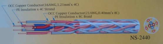
I'm using too a braided construction Neotech cable but capacitance is much lower than CAT5/6 speaker cables...
The NS-2440 has around 200pF/m Vs NS-1952 108pF/m
A braided CAT5 cable (16 conductor) should have around 700pF/m capacitance...
Attachments
I'm using too a braided construction Neotech cable but capacitance is much lower than CAT5/6 speaker cables...
The NS-2440 has around 200pF/m Vs NS-1952 108pF/m
A braided CAT5 cable (16 conductor) should have around 700pF/m capacitance...
I think I'm missing something. Please explain where I am going wrong.
First, I wish I knew where the audio range capacitance of a CAT5 cable really is. 700 pF/m is higher than any quotation I've seen. The CAT5 spec is for less than 52 pF/m for the full CAT5 cable, but is only measured at 800 Hz. I have no idea what happens at higher frequency, but the cable is rated at a corner frequency of 57 kHz. Not bad.
My idea was to strip out either a single twisted pair or maybe 2 pair to use as a hook-up wire. Shouldn't that be a lot lower capacitance than a 16 conductor braided cable?
Just looking for understanding.
Jac
Are you writing about IC's or just the internal hook-up? I tried twisted pair Cat 5 for IC's and it was flat, dull, lifeless. Even using very good (Furutech OCC copper center pin) RCA's didn't help. Neotech OCC copper/teflon wire twisted, spaced pair is the way to go. 24ga is big enough.
I never liked the sound of silver plated copper except for bass speaker cable. I found Kimber TCSS wire to be shrill, but many people like it.
For internal hook-up I use 24ga OCC copper/teflon for signal and ground. I think the quality of the connectors is just as important as a couple inches of hook-up wire. I don't think the geometry inside the amp is all that important unless it is a long run or near mains power. In my amps, signal and ground wires are not even near each other (although they are very short), and the amps are silent. I never detected inherent directionality (it seems to become directional with use, but can be reversed), but I don't mean to start a debate about it. Been there.
But before investing so much time and effort in minor details, you should probably concentrate on just getting the amps put together and running. Plenty of time to tweak afterwards. You just put more pressure on yourself this way, and if something goes wrong, it will be far more frustrating. Build the amps. Listen to music for a couple weeks, then start fine tuning. Really, they do not need to have every perfect part in them to sound good right away.
Peace,
Tom E
Last edited:
I think I'm missing something. Please explain where I am going wrong.
(...)
My idea was to strip out either a single twisted pair or maybe 2 pair to use as a hook-up wire. Shouldn't that be a lot lower capacitance than a 16 conductor braided cable?
My fault, I assumed you were talking about speaker cable...
CAT5 wire will obviously work fine for internal signal wiring but it tends to be less detailed and 'alive' than good quality wire.
But before investing so much time and effort in minor details, you should probably concentrate on just getting the amps put together and running. Plenty of time to tweak afterwards. You just put more pressure on yourself this way, and if something goes wrong, it will be far more frustrating. Build the amps. Listen to music for a couple weeks, then start fine tuning. Really, they do not need to have every perfect part in them to sound good right away.

................... Build the amps. Listen to music for a couple weeks, then start fine tuning. Really, they do not need to have every perfect part in them to sound good right away.
Peace,
Tom E
I couldn't agree more. The ridiculously large number of options in amp construction on top of associated equipment choices make me believe "Tuning" to personal preferences is more significant than I would have suspected. Though I'll probably never do it, I've even considered a selector switch for various flavors of input caps to match different styles of music within my own library. I suppose one could even extend that idea to ICs, hook-up wire and speaker cables . (Would't that be pretty
)In any case, the public BOM approach Dario has taken has the potential to get as close to a universal starting point that will help all of us better understand the effects of all the other options. I have really enjoyed building as much as I can "stock" and then being able to clearly appreciate/hear what an alternate gizmo does.
this does not seem right !I did not realize that a twisted pair could have the same noise rejection benefits with the current going the same direction. I thought they had to oppose each other.
this does not seem right !
Which part? I am curious about this, especially in this and other amps where the inputs and output pairs are a distance from each other on the pcb.
A twisted pair of Flow and Return MUST have opposing currents in the pair.
It is the opposing currents that gives the cancellation of fields in the far distance.
It is the twisting that gives substantial cancellation in the near distance.
Which post did you find that the currents do not need to be "opposing"?
It is the opposing currents that gives the cancellation of fields in the far distance.
It is the twisting that gives substantial cancellation in the near distance.
Which post did you find that the currents do not need to be "opposing"?
This thought was in reference to the post that this post http://www.diyaudio.com/forums/chip...-edition-rc-build-thread-114.html#post3446785 was refering to.
post1136 is referring to a two wire "Return" instead of a one wire "Return".
Are you familiar with a screened star quad microphone cable?
I built up an unscreened star quad using 2pairs of Cat5 twisted together. It performed very well even though the capacitance of the 3m interconnect would be roughly doubled. I could pass this Power Amp input cable around and over transformers and other switched on equipment and could not measure any change in hum or buzz at the speakers.
The Quad star achieves better attenuation of interference, than twisted pair, because the Physical Centroid of each pair in the star quad is at the physical "middle" of the 4wire arrangement. It is the co-incident Physical Centroids that reduces the loop area to near zero.
A two wire Return along diametrically opposite sides of the capacitor is trying to achieve the same Physical Centroid following the Centroid of the Capacitor.
BUT the Return current is still opposed to the Flow current. That is fundamental to low loop area.
Last edited:
Ok, this makes more sense to me, for some reason I thought you were suggesting that a twisted pair run along side the cap. Now I see what you are saying about running one wire on either side( read diametrically opposed) of the cap and the rejoin them beyond the cap. Now should the second wire be spliced into the first after passing the cap essentially forming a y? Or should the return be be two wires over the entire run from rca to pcb returning to a twisted pair after passing the cap? In both instances does the wire gauge need to be decreased to add up to a single run equivalent?
Thanks Andrew
) of the cap and the rejoin them beyond the cap. Now should the second wire be spliced into the first after passing the cap essentially forming a y? Or should the return be be two wires over the entire run from rca to pcb returning to a twisted pair after passing the cap? In both instances does the wire gauge need to be decreased to add up to a single run equivalent?Thanks Andrew
- Home
- Amplifiers
- Chip Amps
- My_Ref Fremen Edition - Build thread and tutorial