...AndrewT, please go on the serbian forum and use google translate to see by yourself before posting such a (...?) fast interpretation. You'll see how cooperatly all has been done, and the high level of some of their users. Of course, it's a long thread, there is 1740 answers ^^. And there is too some parrallel projects on others threads. Just create a account, and have fun : Bato MM-Amp (LM-most by macolakg)
You'll see different kind of test have been done, and a looooooooot of things have been yet discussed. I mean, this question has probably already been disscussed there, but it's really hard using translate too to find in such a big thread answers to such a precise question. It's a cool thread, with cool people trying to just sharing the same hobby.
MODERATORS : don't know how, but can I suggest to do something, like merging in this thread this one : http://forum.yu3ma.net/showthread.php?tid=338&page=87
Last edited:
Hello, I have had a glimpse at the mentioned serbian forum regarding the usage of primary output as input for the second inverter.
A loselly translation of a forum member is following: "The catch is because this way a closed loop is formed. Without this connection the second LME chip would behave just as a preamp and it would have no idea what is the other LM chip doing. Further more, the LME chip can correct the errors which were introduced by the LM chip."
I find this explanation utterly illogical..
The point is that one side LME chip correct errors of "his" LM chip. So no matter if it is taken after the LM. This part is ok. The thing about closed loop...don't know...
It seems that there is other version on the serbian forum using single to balanced chip. But from what i have understood, bato-mm has also be design in low cost/simplicity mind, that should explain easily.
It seems that there is other version on the serbian forum using single to balanced chip. But from what i have understood, bato-mm has also be design in low cost/simplicity mind, that should explain easily.
And you copied his design without trying to evaluate it !!!!
that same man has given me a pair of both op-amps from the schematic, all four of LM3886 and both EI transformers built into the first amp of this ever built on a pcb or any other amp after Macola did it in a 3D (components in air), and even that first pcb came to the light of a day by Macola 's suggestions - and now you tell me that i copied something?! come on...the man invented it and i realised it how he wanted and guided me,i do this for fun, not ti impress anyone or to make money on it and so does Macola , so please relax,ok?
Received !
I'm a bit curious, I didn't notice on gerber files, can you explain the use of this track :
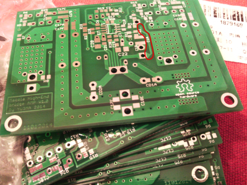
It seems connecting nowhere, there's no vias...it's same in gerber file... its a ground track connecting nowhere... maybe a shield track protecting from out- track????
Hehe
I made that track. Output contact is very close to input so I try to isolate them on such way. There is also ground plane on other side of PCB for same reason.Can you explain ? which video ?Hahaha! Nisam ranije to video...

I will believe you, even if google translate it as "I did earlier this video"
Don't click there,it's a editor bug...if a mod can remove it, i didn't managed... => Don't
My "google"English to Serbian translate it as : "I had not seen it." Try again.
My "google"English to Serbian translate it as : "I had not seen it." Try again.
i have allready answered what my friend said in that post:
BC109, avoid writting in serbian it is forbidden by the rules of the forum....
.
papasteac, what he said was "I haven't seen that",and he ment on the little peace of ground lead that Yu3ma(the smd pcb author) explained two posts earlier.
One small corection regarding formula for calculating resistor value R23 and R24 (resistor for 12V zener diode), on original shematic is specified 10mA current but need to be 20mA!
Intersting thing is that LME even with wrong value for those resistors which lead to unstabilised +/-12V (zener diode don't have efect) still works great due it's very good PSRR
Intersting thing is that LME even with wrong value for those resistors which lead to unstabilised +/-12V (zener diode don't have efect) still works great due it's very good PSRR
- Status
- This old topic is closed. If you want to reopen this topic, contact a moderator using the "Report Post" button.
- Home
- Amplifiers
- Chip Amps
- BatoMM amp.LM-bridge,consider to try it...