Hi,
I am not very good with electronics but I try to read up and piece stuff together. Could someone help me out, any suggestion or changes that I should make? Also I've heard that there should not be a huge capacitor before a op amp input due to stability could anyone explain to me this and what value of caps I should use?
All the resistors labeled 20k or 40k ohm would be controlled by multiple AD5144 100k digi pot to save space it comes in a quad package and a tolerance level of 8%, I think that should be okay, if not it will be AD5271 but it only comes in a single package but has 1% tolerance.
I will also be using is a microcontroller with 2SPI either a TI or Mircochip brand, to control the pots, a rotary encoder and a LCD like this MC20805B6W-FPTLW - MIDAS - LCD, 2X8, FSTN, WHITE LED B/L | element14 Singapore
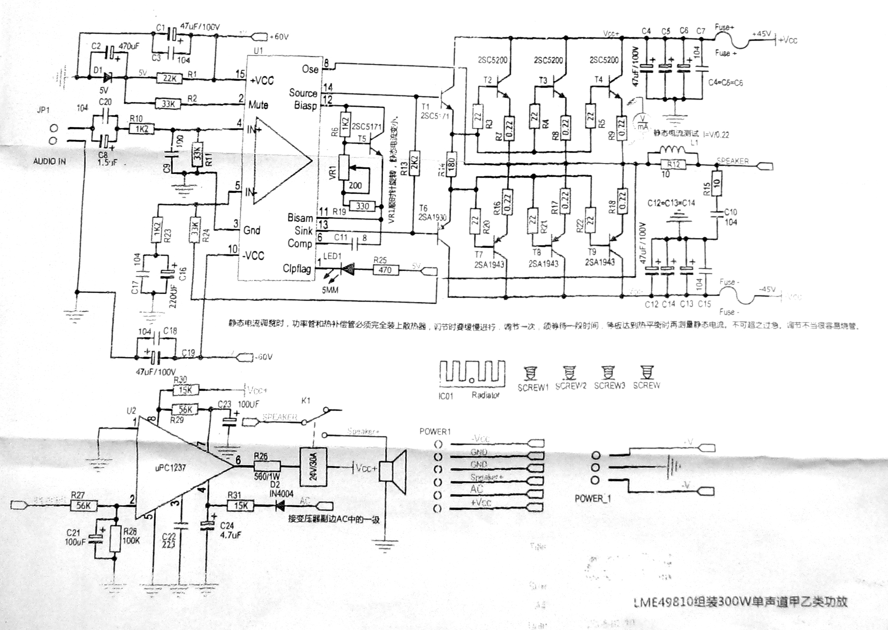
I have checked that all the outputs are in phase and that the subwoofer out will be connected to this 300W power amp from here http://www.diyaudio.com/forums/solid-state/155173-anyone-recognise-design-based-lme49810.html and Schematics here
It will be powered by a Connexelectronic SMPS300RE with +/-45V rails and a aux +/-15V for the opamps and a ldo drop to 3.3v for the MCU and the pots
Any comments and will it work? op-amps are opa4134 quad package
Thanks
I am not very good with electronics but I try to read up and piece stuff together. Could someone help me out, any suggestion or changes that I should make? Also I've heard that there should not be a huge capacitor before a op amp input due to stability could anyone explain to me this and what value of caps I should use?
All the resistors labeled 20k or 40k ohm would be controlled by multiple AD5144 100k digi pot to save space it comes in a quad package and a tolerance level of 8%, I think that should be okay, if not it will be AD5271 but it only comes in a single package but has 1% tolerance.
I will also be using is a microcontroller with 2SPI either a TI or Mircochip brand, to control the pots, a rotary encoder and a LCD like this MC20805B6W-FPTLW - MIDAS - LCD, 2X8, FSTN, WHITE LED B/L | element14 Singapore
I have checked that all the outputs are in phase and that the subwoofer out will be connected to this 300W power amp from here http://www.diyaudio.com/forums/solid-state/155173-anyone-recognise-design-based-lme49810.html and Schematics here
It will be powered by a Connexelectronic SMPS300RE with +/-45V rails and a aux +/-15V for the opamps and a ldo drop to 3.3v for the MCU and the pots
Any comments and will it work? op-amps are opa4134 quad package
Thanks
Attachments
Last edited:
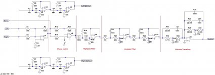
The values around U1 and U6 concern me a bit. As high as they are, 100K, there will be a parasitic pole at the input that may make U1 and U6 into oscillators somewhere between 100 kHz and 1 MHz. Quickest fix might be to drop the resistors to 10K, and be careful about the layout around the inverting inputs. (a small cap across the feedback resistor(s) is another approach).
The instability concern you refer to is more typically associated with large capacitive loads on the outputs of the opamps...your design seems ok in that regard.
Lastly, you didn't show power supply bypass caps for the opamps...I'm guessing that you are planning on such bypass caps, but left them off for the sake of clarity in the drawing.
Update My Dynaco
Akitika GT-101 Audio Power Amplifier Kit
Haha I like my stuff neat and tidy. ThanksFor somebody "not very good with electronics" you draw a helluva schematic. Just noticing.
Oh wait, I just noticed you're from Singapore. In English, in this context, "helluva" means good.
")
Thanks for the help!The values around U1 and U6 concern me a bit. As high as they are, 100K, there will be a parasitic pole at the input that may make U1 and U6 into oscillators somewhere between 100 kHz and 1 MHz. Quickest fix might be to drop the resistors to 10K, and be careful about the layout around the inverting inputs. (a small cap across the feedback resistor(s) is another approach).
The instability concern you refer to is more typically associated with large capacitive loads on the outputs of the opamps...your design seems ok in that regard.
Lastly, you didn't show power supply bypass caps for the opamps...I'm guessing that you are planning on such bypass caps, but left them off for the sake of clarity in the drawing.
Update My Dynaco
Akitika GT-101 Audio Power Amplifier Kit
I have dropped the 100k resistors to 10k on the inputs they should do fine. For the highpass filter, should I be upping the C9 and C10 values so that I could reduce the resistor value of R16 like so in the picture? Will that be alright or should I change it back to orginal.
I am also software limiting the digi pot so that Rvar value will be in range of 10k to 45k range. And typical usage will be from 15k to 30k, my main speaker cant go below 55Hz.
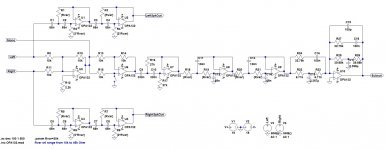
Yup you are right I didnt show the caps in the drawing but here it is,
U1 to U4 would be in one quad package, OPA4132, while U5 and U6 would be in a single dual package, OPA4132, followed by U7-10 which will also be in a OPA4132. Each package supply would be bypass at it's pins by a 100nF ceramic cap followed by a 47uF alu cap. and a overall bypass for all the op-amps by a 100uf alu. not including the bypass at the LDO.
Hope I got everything correct. And anyone knows whats the best way to add a gain control for the subout line?
Attachments
That Linkwitz transform will of course only work for the drivers it was designed for in a box of the same size? If you have different drivers then you can pick up a good spreadsheet to calculate values from Rod Elliot's site Elliott Sound Products - The Audio Pages (Main Index).
Not sure I would use the OPA132, though. But that's another topic ... (A safe bet alternative would be the OPA604 or, for more compact layout, its dual, the 2604.) It matters not a jot for the subwoofer, but it might for the high passes going to your speakers.
Not sure I would use the OPA132, though. But that's another topic ... (A safe bet alternative would be the OPA604 or, for more compact layout, its dual, the 2604.) It matters not a jot for the subwoofer, but it might for the high passes going to your speakers.
That Linkwitz transform will of course only work for the drivers it was designed for in a box of the same size? If you have different drivers then you can pick up a good spreadsheet to calculate values from Rod Elliot's site Elliott Sound Products - The Audio Pages (Main Index).
Not sure I would use the OPA132, though. But that's another topic ... (A safe bet alternative would be the OPA604 or, for more compact layout, its dual, the 2604.) It matters not a jot for the subwoofer, but it might for the high passes going to your speakers.
Hey thanks for replying to both my threads, if you noticed.
Yes the linkwitz tranform circuit is a calculated one specific to my driver and box size. My worry is not so much the transform circuit itself but whether the circuit as a whole will work fine without any oscillations.
I think I will heed your advice and change the op amp for the highpass filters. I will leave the opa132 if it's okay for the bass section. But may I know what's your rationale behind this? I am guessing its not a bandwidth issue but something else.
May I also know your opinion on using opa627. Heard they are better then the 604.
Thanks
Hey thanks for replying to both my threads, if you noticed.
I think I will heed your advice and change the op amp for the highpass filters. I will leave the opa132 if it's okay for the bass section. But may I know what's your rationale behind this? I am guessing its not a bandwidth issue but something else.
May I also know your opinion on using opa627. Heard they are better then the 604.
Thanks
Yup, the OPA132 is fine for the subwoofer - you could easily get away with a TLO71 in that role (an op amp that I happen to like, BTW)
Like you I'm told that the 627 is better, but I haven't tried one - far too expensive and I'm actually not a huge fan of the 2604, finding it a bit too boring and close to indistinguishable from the 5532 (which you probably can't use here, with all those high value Rs). But others seem to like it and I've heard it in products that I genuinely do like.
Having said that it might be that the designer picked the OPA132 as a compromise in price between what is needed for the high pass and not wasting money on the sub while using the same op amp throughout. No harm though in having a handful of TLO71s or LF353s around to put in the circuit as testers - they are not much more than about 8p each.
- Status
- This old topic is closed. If you want to reopen this topic, contact a moderator using the "Report Post" button.
- Home
- Amplifiers
- Chip Amps
- LR crossover, linwitz transform and LME49810? Some help for me