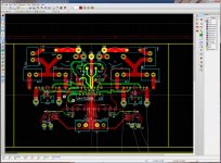
I've attached a screenshot of my progress so far on an LM4072 + STD03N/P output amp. Also the project, in kicad.
It's got a DC servo simulated in LTspice, is pretty much all surface mount except power output components, and is just about ready to rock n roll.
I've kept fairly close to the reference design, but my layout is more symmetrical in comparison. Started out with 80 x 160mm boards for PSU and amp sections, but the amp board can be a bit smaller. Might bung in a third pre-amp or speaker protection board before I get some of these fabbed externally.
Not seen this combo before with a quick search, or much about biasing STD03s, although they seem popular. So, some of the values are placeholders, and the large SMD footprint CI caps (47uF) are meant to be stacked a couple high for instance, for a quick n dirty 100uF replacement which gets a bit pricy for SMD, for example.
Comments welcome")
It's got a DC servo simulated in LTspice, is pretty much all surface mount except power output components, and is just about ready to rock n roll.
I've kept fairly close to the reference design, but my layout is more symmetrical in comparison. Started out with 80 x 160mm boards for PSU and amp sections, but the amp board can be a bit smaller. Might bung in a third pre-amp or speaker protection board before I get some of these fabbed externally.
Not seen this combo before with a quick search, or much about biasing STD03s, although they seem popular. So, some of the values are placeholders, and the large SMD footprint CI caps (47uF) are meant to be stacked a couple high for instance, for a quick n dirty 100uF replacement which gets a bit pricy for SMD, for example.
Comments welcome
Attachments
Well, my thinking on that issue - and it has been considered - is that it doesn't need one, unless you know / have experience that says otherwise? I'll admit my analog design isn't the best, I'm more mixed signal / digital / RF.
So, what I did was routed the grounds to a central point, basically using a star routing methodology to avoid ground loops. This thing is going to be in a metal case, so doesn't need a ground plane for immunity reasons as far as I can see.
Also, if I employed a ground plane here, wouldn't that result in stray capacitance to the tracks on the opposite side of the board? If you look at National's design here: http://www.ti.com/litv/pdf/snaa031 the recommended PCB layout doesn't include ground planes either.
What they do do is shield the toroidal transformers with mu-metal, and comment on track lengths being an important factor - more than 0.1mm diversion meant measurable distortion, apparently.
So, I've stuck to the same sort of methods National employed, but using surface mount and STD03 pairs + biasing. This is why you can see Vcc / Vee points variously on the board as well, the same kind of star routing for PSU, and the speaker grounds also.
If you can find holes in my reasoning, then I'd appreciate feedback, as it'd be good to try and improve on national's design. I've also got some LME49810s/30s sitting about waiting for a project - most probably a six-pack of some sort! I'll get this working first though
Without a ground plane, at least for the input signal and input signal ground section, you will have to worry about creating enclosed loop area between signal and signal ground, which makes a good receiving antenna for time-varying magnetic fields, such as from your AC Mains pair and transformer secondary pairs, if they are not perfectly tight together and twisted from end to end (not to mention the transformer itself), and... RF. Every other pair of conductors that has ANY space enclosed will either be a receiving or transmitting antenna. Any with time-varying current will transmit a time-varying magnetic field, which will induce current in other loops with any enclosed area. (See "Faraday's Law", or Maxwell's Equations.) Think all of your power rails and ground returns have zero enclosed loop area? That would be difficult to achieve, without four or more layers with planes.
Anyway, the one place where is really does matter is the low-level input section, since anything picked up there is sent straight into a high-gain power amplifier! The best way to minimize the enclosed loop area is to use a ground plane for the signal input ground, from where it enters the pcb all the way to wherever it goes. But DON'T connect it to any of the other grounds, except at the star ground.
Anyway, the one place where is really does matter is the low-level input section, since anything picked up there is sent straight into a high-gain power amplifier! The best way to minimize the enclosed loop area is to use a ground plane for the signal input ground, from where it enters the pcb all the way to wherever it goes. But DON'T connect it to any of the other grounds, except at the star ground.
I think that's why national shielded their transformers with mu metal. As you say, not connecting the ground plane for signal ground at any point except star ground is important.
As for RF, it's in a metal box, and will have a filtered IEC socket on the mains inlet. Supply is bypassed at various points as well. No clocked digital circuitry, attention paid to zobel network from speakers, signals routed internally through carefully grounded and shielded co-ax cable...
The above is based on National's own advice:
I shall see over the next few weeks anyway, and report back. One of my other projects is a distortion meter, as I want to see the effects choices like ground plane / no ground plane have on a design.
As for RF, it's in a metal box, and will have a filtered IEC socket on the mains inlet. Supply is bypassed at various points as well. No clocked digital circuitry, attention paid to zobel network from speakers, signals routed internally through carefully grounded and shielded co-ax cable...
The above is based on National's own advice:
Wiring techniques can have an effect on sound quality. Point to point wiring, star ground and star power
routing of supply wires will improve noise measurements and have an effect on perceived “sound quality”.
Large gauge wire will reduce IR losses (Current X Resistance losses) and thus improve amplifier
efficiency slightly. Also good connections are a basic requirement in properly constructed power amplifier.
I shall see over the next few weeks anyway, and report back. One of my other projects is a distortion meter, as I want to see the effects choices like ground plane / no ground plane have on a design.
I can tell you a couple of things the LM4702 and its kin seem to like -- decouple the power supply pins immediately adjacent to the chip -- the ground side of the decoupling caps should be attached to the ground plane cited above.
The compensation cap is specified at 30pF -- you can use a lower value for higher slew rate at the risk of instability -- the model for TINA doesn't give a clue to the appropriate value -- and the application note dealing with this issue wasn't written after National laid off a bunch of the design team.
Leave sufficient space to heat sink the LM4702 -- nothing enormous -- even some aluminum sheet of a couple square inches improves the performance.
Saying all the above, I got better measured performance out of the amplifier with the TIP147/142 Darlingtons than the Sankens. Nicest sounding, to these old ears, were the amps using lateral mosfets == and these seemed easiest to bias with no thermal issues.
EDIT: I am building one using OPA2604 as a buffer/inverter so as to run the LM4702 inverted with gain of 26dB. OPA134 as servo.
Last edited:
I think that's why national shielded their transformers with mu metal. As you say, not connecting the ground plane for signal ground at any point except star ground is important.
As for RF, it's in a metal box, and will have a filtered IEC socket on the mains inlet. Supply is bypassed at various points as well. No clocked digital circuitry, attention paid to zobel network from speakers, signals routed internally through carefully grounded and shielded co-ax cable...
The above is based on National's own advice:
I shall see over the next few weeks anyway, and report back. One of my other projects is a distortion meter, as I want to see the effects choices like ground plane / no ground plane have on a design.
I should learn to make only one point at a time. (And I'm sorry if I've already mentioned some of the following.)
All of the wiring and traces between the AC input and the reservoir capacitors could emit strong time-varying fields. All of the wiring and traces between the signal inputs and the chip input pins could have currents induced in them by time-varying fields.
How well they transmit or receive will be proportional to the amount of geometric area enclosed by the loop formed by each pair of conductors.
Since you are not wanting to use a ground plane for the signal and signal ground input section of the PCB, you should take special care to ensure that the signal and signal ground do not separate, anywhere, by more than a millimeter or two, and preferably less. Also, use tightly-twisted pair for them, all the way from the PCB to the jacks. Shielded twisted pair would be best, with the shield connected to chassis (and not signal ground!) only at the input end. And do not electrically connect any part of the input jacks to the chassis.
The AC and rectified AC wiring and traces should be treated the same way. Tightly twist together each pair, ALL the way to each end; say four turns per inch or more. And if one AC input wire has to go to a switch, then both must go, for example. Also don't separate the wires or traces that go from the recitifiers to the smoothing caps.
- Status
- This old topic is closed. If you want to reopen this topic, contact a moderator using the "Report Post" button.
- Home
- Amplifiers
- Chip Amps
- LM4702 + STD03s