LM3875 + Broskie Cathode Follower. (WITH PICS)
Hi folks.
I havn't posted anything for a while but have still been active with the soldering iron.
Having built several LM3875 amps either using the excellent Peter Daniels kits or P2P and following what National recomend i like the amp. My system at home is based around a pair of 1200's and a analogue dj type mixer. I also use an analogue Phonic studio mixer and a pc running Traktor scratch pro for the decks, utillising time code vinyl.
Ive always been aware of balanced audio inputs / outputs and understand the principles of the differential amplifier / buffer. As both my mixers have xlr balanced outputs i decided to upgrade my system to balanced.
As well as this ive been tinkering with valves and finally decided to build something using them. I went through the usual hrs of looking at buffers and pre-amps using triodes etc. Nearly all i found coupled to an LM3875 were in the inverted setup. I was keen to use Audio sector boards for the output amps and they are non inverting. I then looked at the Broskie Cathode Follower. It seemed perfect for all my requirements.
LM3875 non inverted PD kit.
Balanced to un-balanced buffer.
Good starter for valve project.
The project is almost finished. I tested it and every thing was better than i expected except i roughed the valve buffer out with salvaged components first time round and had few mis matches so ive re built that section.
Over next few post il put up photos and diary etc
Last edited:
The project is housed in a 19 inch rack mount 3u case which i liberated from a cheap chinese amp. (chassis was surprisingly good).
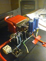
I used two traffos. The B+ comes from a traffo that powered a small valve tape recorder that came from a skip. It powered a dual triode using a voltage doubler so thats what i did. The traffo for the LM3875's came from a kenwood stereo. It has multiple secondaries. 23-0-23 is powering the chips and 12v rectified for the valve heaters. This is due to me using 6H1N valves and the valve traffo's heater winding wasn't great.
I used two traffos. The B+ comes from a traffo that powered a small valve tape recorder that came from a skip. It powered a dual triode using a voltage doubler so thats what i did. The traffo for the LM3875's came from a kenwood stereo. It has multiple secondaries. 23-0-23 is powering the chips and 12v rectified for the valve heaters. This is due to me using 6H1N valves and the valve traffo's heater winding wasn't great.
The can type rectifier in the first pic was used to test the heater circuit. it has since been removed and replaced with a board containing MUR860 diodes and some electrolytics. This cicuit running from the red traffo is 12v dc and draws a constant 520mA. This is with the heaters in series. The datasheets suggest 12.6vdc @ 600mA +/- 50mA. Im confident im close enough, if anyone can advise me further on this please do. Ive decoupled the heater pins on each valve with poly cap.
The thick red cable is for the mains inlet, switch and traffo's. I scrounged it off the guys who came to fit fire detectors in my block of flats. It is mains rated twin plus earth solid core with a metal fire shield and bloody brilliant for any mains connections.
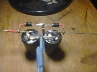
The big blue caps are the main supply caps for the 3875's (10,000uf 43v) with a small poly underneath the board and 2.2k resistors to bleed the caps. The "underneath" of this board also holds 4 mur860's arranged for a center tapped secondary.
The big blue caps are the main supply caps for the 3875's (10,000uf 43v) with a small poly underneath the board and 2.2k resistors to bleed the caps. The "underneath" of this board also holds 4 mur860's arranged for a center tapped secondary.
Since a good cathode follower should ideally do nothing but provide a lower output impedance than input impedance, what function does this perform? The LM3875 already has a very high input impedance.
It might have been more interesting to try Broskie's Super Triode:
SuperTriodes & Inverted ES Speakers
It might have been more interesting to try Broskie's Super Triode:
SuperTriodes & Inverted ES Speakers
It might have been more interesting to try Broskie's Super Triode:
SuperTriodes & Inverted ES Speakers
Hello Fenris
JR Broskie wrote " we must also increase the 520-ohm feedback resistor to ensure that the solid-state amplifier’s gain exceeds the triode’s mu. In the example shown above, the feedback resistor’s value has been increased to 100k, which results in a gain of 100 for the solid-state amplifier "
The triode 6dj8 has mu value of 33, do you know the reason why JRB has choosen a very hight gain of 100, and not ~40 - 50 ?
Thanks
It lets the builder say there's a tube in there!Since a good cathode follower should ideally do nothing but provide a lower output impedance than input impedance, what function does this perform? The LM3875 already has a very high input impedance.
It might have been more interesting to try Broskie's Super Triode:
SuperTriodes & Inverted ES Speakers
Or this one ?
http://www.tubecad.com/2008/04/27/aikido gainclone hybrid design 1.png
Thanks for this - it looks very good in simulation with JFETs instead of Triodes, and an opamp instead of a chipamp. Basically, a solid-state mini-Aikido for driving heaphones.
Hello Fenris
JR Broskie wrote " we must also increase the 520-ohm feedback resistor to ensure that the solid-state amplifier’s gain exceeds the triode’s mu. In the example shown above, the feedback resistor’s value has been increased to 100k, which results in a gain of 100 for the solid-state amplifier "
The triode 6dj8 has mu value of 33, do you know the reason why JRB has choosen a very hight gain of 100, and not ~40 - 50 ?
Thanks
The 100K keeps too much current from flowing from the ouput of the opamp to the cathode of the tube. The ideal cathode load would be infinite, with a 100K plus the 1K in parallel with the 1M and 10K, it's an overall cathode load of 91K. The CCS keeps sufficient current flowing through the tube to operate it in the linear range. You might be able to change the 1K to 2K and the 10K to 20K. The high opamp gain may be to maintain a good phase margin, or could be overdesign to ensure that the tube gain is never more than the opamp gain.
I'm building one of these now and am about 95% done, but won't be able to finish for about another 7 months due to life.
I'm building one of these now and am about 95% done, but won't be able to finish for about another 7 months due to life.
Thanks for detailled explanations !
Which chip did you choose ?
LM3886 ? seems to be better about distorsion
LM3875/LM3876 ? seems to be more appreciated about soundings
R.C.
With the LM3886 and 3875, high gain and feedback resistors invite oscillation -- with the LM4702 driver chip, there's a pin for compensation.
I simmed the circuit in your post and you'll have to compensate it just a bit around the LM3886.
- Status
- This old topic is closed. If you want to reopen this topic, contact a moderator using the "Report Post" button.
- Home
- Amplifiers
- Chip Amps
- LM3875 + Broskie Cathode Follower.

