there's a website that has an automatic calculator for this, and it works really nice. Just sharing in case you have a bad room like mine, near field can be the way to go.
Interesting, thanks Jonathan. Could you PM me a link to the website please?
Very OT, but bonjonno's post made me wonder about speaker placement and imaging. When there are stuff like TV cabinets or other furniture between (and close to) stereo speakers - does that have a negative effect on the soundstage and imaging?
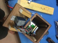
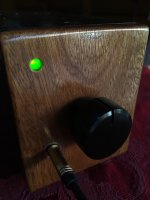
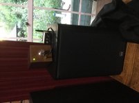
Just thought I would share my TDA7297 build. Just a bit of fun. Not an audiophile.
I bought an assembled PCB on line and used timber scraps and few common electrical parts for the case.
I performed the recommended capacitor additions and upgrades, changed the volume pot, and put it in a minimalist enclosure.
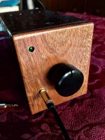
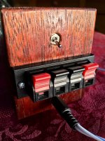
At the back is a speaker terminal block, power switch and power jack (5.5x2.5). On the front panel I have added the power LED and 3.5mm input jack, as well as the volume pot (not sure I like the black).
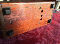
Inside I changed the LED to a low intensity 5mm green without changing the onboard current limiting resistor. Vent holes top and bottom neat the heat sink.
Currently running off a small 7.5AH VRLA 12 battery.
Into a pair of Warfdale 415 100w 8ohm 87dB bookeshelf speakers the amp draws max 1.87A at 12.5V that is 23.4 Watts peak consumption measured at he battery. Inrush current is 17.5A. I had the iPhone at max volume playing Brothers In Arms.
Reasonably loud in a small room.
Any suggestions for a nicer volume dial? Once have decided on one I will trim the pot to length.
Cheers
I bought an assembled PCB on line and used timber scraps and few common electrical parts for the case.
I performed the recommended capacitor additions and upgrades, changed the volume pot, and put it in a minimalist enclosure.
At the back is a speaker terminal block, power switch and power jack (5.5x2.5). On the front panel I have added the power LED and 3.5mm input jack, as well as the volume pot (not sure I like the black).
Inside I changed the LED to a low intensity 5mm green without changing the onboard current limiting resistor. Vent holes top and bottom neat the heat sink.
Currently running off a small 7.5AH VRLA 12 battery.
Into a pair of Warfdale 415 100w 8ohm 87dB bookeshelf speakers the amp draws max 1.87A at 12.5V that is 23.4 Watts peak consumption measured at he battery. Inrush current is 17.5A. I had the iPhone at max volume playing Brothers In Arms.
Reasonably loud in a small room.
Any suggestions for a nicer volume dial? Once have decided on one I will trim the pot to length.
Cheers
Attachments
-
 80BC58AC-CAB3-48AF-8B18-09D938701D48.jpeg661.8 KB · Views: 587
 -
 A8CD4C4F-21D2-4A7E-A589-45F4F35A4E5D.jpg409.8 KB · Views: 579
 -
 A8393BB3-CD54-4BA5-902E-81B867E0A359.jpg436.6 KB · Views: 556
 -
 A504CB18-A243-4334-8345-904BA5B8B96D.jpg522.6 KB · Views: 538
 -
 B745AC29-4E66-491E-92A4-DE8C589565AA.jpeg535.5 KB · Views: 498
I’d maybe like to make a pair of speakers and a regulated linear power supply to go with this.
Does anyone have any suggestions (off the shelf, kits, specs, etc) on either?
Thanks
Cool build. If you want to continue with the theme of mighty sound in a small package, you might look into speaker designs built around the Aura NS3 or Dayton's versions of the same driver, ND90. They perform unbelievably well for their size, especially as near field monitors. A couple popular full range projects are the Carmody Sprite (which I built) and Wolf PC speakers. A popular build adding a tweeter is the Helium. There is another one out there using a planar tweeter even, which I hope to try. Check the PE forums for lots of examples.
Sorry, I didn't consider your location. I think the driver I mentioned would blow the doors off of B452 or pretty much any other cheap drivers under 6.5". They have crazy excursion. AFAIK the OS plays in a higher class. It uses pretty nice drivers, packs unusual bass for its size, and its sound is definitely well loved by many.
Well, it's more about playing it safe. For 4$ a chip. That's what I did. I don't say that they are, for sure. As I don't know. I can only speculate. Based on some math, seeing the price of a chip from a trusty distributer etc.
Once again, I can't know for sure, because I don't know what to look for when testing two against each-other. The producer might have some standards regarding some characteristics that I don't know about and can't test anyway. That kind of testing might reject some chip.
Think of it this way, these chips are used in TV's or some other kind of mass market application. If the chip doesn't meet some strict characteristics, and Samsung releases hundreds of thousands of TV's with a chip that fails prematurely, it's bad for the producer of the chip.
So then you can have perfectly sounding chips, that are sold on ebay for real cheap, but they fail past 17-18V on the supply. Or some other kink..
Of course this is just speculation.
Or you can find out here that this chip sounds real nice, and then decide to build your own amp with it.
Nothing wrong with that. It's still cheap, 4$ for the chip, some FC electrolytic caps, two Wima's for signal and a pcb (that's cheap at any pcb fab house). Won't cost you a fortune, have a guaranteed original chip and can enjoy the music.
Here's my pcb design for this amp. I made it with the help of danielwritesbac, without him I couldn't have done it like this. I post it so anyone can make it and enjoy it, as I am!
Hi Bob, I decided to place an order at allpcb.com, with your design. I think they do a fantastic job on this one, considering the price and the fast turnaround, and shipping to my door.

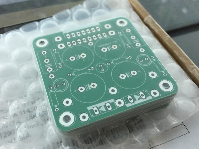
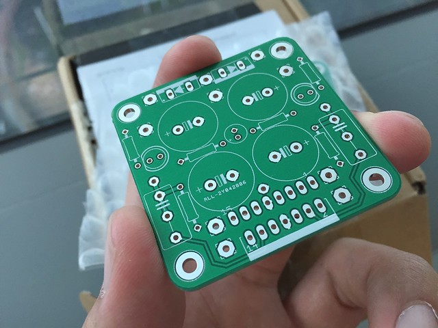
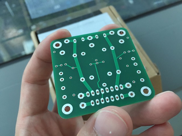
I have 6 boards in total, and may be willing to share to any of you guys at small cost, but maybe ordering direct is cheaper than postage from my city.
")
Looks better with different knob.
Helium speaker parts arrived today.
The port I ordered is a bit larger in diameter than the 3/4” in the original design on the Parts Express forum. This one measure more like 7/8”. Do I have to make a compensation? It is taking weeks to get the administrator to allow me to post on that forum to ask.
Just thought I would share my TDA7297 build. Just a bit of fun. Not an audiophile.
I bought an assembled PCB on line and used timber scraps and few common electrical parts for the case.
I performed the recommended capacitor additions and upgrades, changed the volume pot, and put it in a minimalist enclosure.
At the back is a speaker terminal block, power switch and power jack (5.5x2.5). On the front panel I have added the power LED and 3.5mm input jack, as well as the volume pot (not sure I like the black).
Inside I changed the LED to a low intensity 5mm green without changing the onboard current limiting resistor. Vent holes top and bottom neat the heat sink.
Currently running off a small 7.5AH VRLA 12 battery.
Into a pair of Warfdale 415 100w 8ohm 87dB bookeshelf speakers the amp draws max 1.87A at 12.5V that is 23.4 Watts peak consumption measured at he battery. Inrush current is 17.5A. I had the iPhone at max volume playing Brothers In Arms.
Reasonably loud in a small room.
Any suggestions for a nicer volume dial? Once have decided on one I will trim the pot to length.
Cheers
Attachments
Hi
What about the heat disapation? How you do that? can´t see it on your pics.
figure 9 at the datasheet...
because
i made a test on my TDA7297 DROk board with my freq. generator 20hz to 20khz sweep about 20min. 8 ohms dummy load each channel.
it gets hot -70 °C !!! - after 20minutes with the originally heatsink @12VDC power from my regulated PSU .
kr
chris
What about the heat disapation? How you do that? can´t see it on your pics.
figure 9 at the datasheet...
because
i made a test on my TDA7297 DROk board with my freq. generator 20hz to 20khz sweep about 20min. 8 ohms dummy load each channel.
it gets hot -70 °C !!! - after 20minutes with the originally heatsink
@12VDC power from my regulated PSU .kr
chris
Attachments
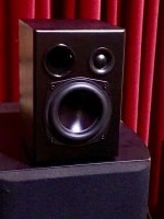
BUilt the Helium speakers. They sound great but might need a beefier amp one day but the volume is loud enough at 80% rotation and no clipping with the little amp. Thanks to Stellarelephant for the speaker build idea. I didn’t think anything so small could produce that much bass!
One question: touching the volume knob creates a bit of hiss when there is no input signal. I am using a SMPS with no earth pin, could that be the problem? Is there a solution? I was thinking about trying to insulate the knob from the pot shaft somehow as a simple solution.
Here is the finished speaker.
I bit the bullet and ordered the components for the Heliums from PE. No cabinets, will make my own.
Attachments
Last edited:
Use some plastic knob.I was thinking about trying to insulate the knob
I have been running in some Helium speakers today at medium volumes for several hours. The room temp is 30C and the temperature inside my wooden enclosure is 60. Actually I think it could easily overheat in these conditions if Impushed the volume up over half way.
Hi
What about the heat disapation? How you do that? can´t see it on your pics.
figure 9 at the datasheet...
because
i made a test on my TDA7297 DROk board with my freq. generator 20hz to 20khz sweep about 20min. 8 ohms dummy load each channel.
it gets hot -70 °C !!! - after 20minutes with the originally heatsink
kr
chris
Last edited:
- Home
- Amplifiers
- Chip Amps
- What the heck? It's less than lunch!