Hello
I have been developing a pre-amp for an electric guitar using op-amps. I emulate valve sounds by using an array of diodes and for a soft "crunch" sound it is perfect. However when trying to provide a thicker distortion I am clipping right at the output of the op-amp and then it is too late to do anything to shape the output curve. Increasing the power supply of course helps but you can only go up to 36 volts in most op-amps.
Is there a way maybe I can use two op-amps like in a cascode way to allow an output swing over 36 volts?
Thanks
simplest is if you have balanced reciever at other end - then bridging doubles the net Vswing
or even simpler - just change system gain structure - add 2x in the guitar amp (just turn it up?)
a line level audio transformer could do the step up too
I have cascaded op amps - not highly recommended for the complexity, possible stability problems
http://www.edn.com/contents/images/45890.pdf is one approach with discrete output
if you have extra sec windings you could make a floating supply amp - can double swing - again uncommon design criteria
adding a discrete transistor gain stage output but inside the op amp feedback loop is more common - but also has stability design requirements
or even simpler - just change system gain structure - add 2x in the guitar amp (just turn it up?)
a line level audio transformer could do the step up too
I have cascaded op amps - not highly recommended for the complexity, possible stability problems
http://www.edn.com/contents/images/45890.pdf is one approach with discrete output
if you have extra sec windings you could make a floating supply amp - can double swing - again uncommon design criteria
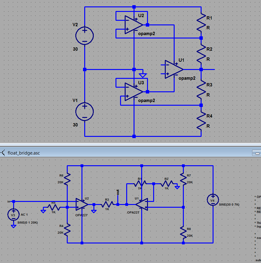
the top is a sketch of cacading op amps for double the V swing - becomes a little complicated
the lower is a sim of one possible bridged floating supply circuit which also doubles Vswing at the cost of requiring a isolated supply (V4 in this sim)
beware of simulating these circuits - the common Boyle op amp macromodel assumes the op amp's output gain stage is connected to spice node 0
this is wrong for floating supply/modulated/bootstrapped supply op amp circuits and can give wrong indications of stable operation where additional compensation is needed
adding a discrete transistor gain stage output but inside the op amp feedback loop is more common - but also has stability design requirements
Last edited:
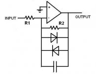
If you are using diodes to get distortion then the output will never swing to the power rails , the diodes clip the output signal to the diode voltage (0.7v for silicon 0.3v for germanium and 1.5v for LED"s) .......
If you want a larger output voltage I would use one opamp stage with clipping diodes then use another opamp gain stage without diodes for makup gain ......
you can also use diodes in series to extend the output voltage before clipping , 2 silicon diodes in series will give you double the output voltage before clipping than a single diode .......
Cheers
I am thinking aloud as I am typing this ")
I am trying to create a solid state guitar pre-amp / amp that sounds like a valve amp, as much as possible. If I cannot reproduce the sound then I will probably go and buy a Mesa Boogie Lonestar and be done with it.
The above valve amp, has a pre-amp voltage gain of Av=50 on the "clean" channel and again, another Av=50 on the "distortion" channel, which is sequential from the clean channel but through a "drive" knob which at best divides by 2, ie Av = 50 * 50/25 = 1250.
We also know that valves have quite a lot of headroom before they clip hard, starting with a smooth rounding of the curve rather than an abrupt clipping.
A Gibson Les Paul Custom at full volume produces 0.7V RMS on a 1M load when strumming hard, and about 0.3V RMS when playing solo sections.
Having run some listening tests, I have arrived at a circuit that uses an array of diodes to compress the output swing in a soft manner, and after some tests we have achieved the best sounding "crunch" (soft overdrive where each note is distinct even when strumming chords) using 6 pairs of BAT48s.
The diode array comes after the op-amp gain stage. Obviously if the gain stage has already clipped, we have lost the game.
With 1V peak and an op-amp stage of Av=50 on the clean channel which has no "drive" knob, we need a voltage swing of +/- 50V which must not be clipped (otherwise it is not clean). This also implies a supply of over +/- 50V. We are approaching then valve-like voltages.
My initial circuit was tested with two 9V batteries, so the available voltage swing was puny. The diode array did its best to smooth the sound, and we did get a great sound, the "crunch" was the best ever my son said, but of course if we have clipped inside the op-amp we are not doing it right.
So just to recap, I need a clean voltage swing of +/-50V to be able to match the valve sound on the pre-amp stage.
OK
Here is how I do it.
go to: DigiKey Electronics - Electronic Components Distributor
search for "amplifier"
gets you 45,169
select "Linear - Amplifiers - Instrumentation, OP Amps, Buffer Amps (32816 items)"
then check the box "in stock"
that gets you 13,067
select number of circuits 1
now 5,772
now go to the far right and select "bulk", "cut tape", and "tube"
now 3,378
now go to "Voltage - Supply, Single/Dual (±)" and scroll to the bottom of the column and select all that can operate at +/- 60V supply or greater.
That left me with 34 choices.
at the top of the column labeled "unit price" click on the arrow pointing up...then select "simple price..." in the popup window.
That is how I would find an opamp for your requirements.
Or get a design for a AF power amp that uses +/-70V rails and don't use a heatsink.
Or use a small power amp and a step-up transformer.
Or drive a diode pair with an AC current source to simulate a high voltage swing/large resistor combination.
Lots of other ways.
My first choice: Current source
R1 5K-10K
R2 1M-10M
A little C to help stability (if required)
Play with the values to get the sound you want.
IMHO
Attachments
Voltage swing has nothing to do with getting a valve type sound , it"s all about getting the right type of clipping then shaping the tone , even if you could get a SS preamp to put out a voltage swing of +/-50v the SS power amp in the next stage couldn't handle the signal as most SS power amps expect a 0.7v-1v line level input signal and 100v would clip the power amp like crazy or even fry it ......
There several preamps out there that have a tubeish sound that run off of as little as 9v and have less than +/-4.5v output swing though I have found the best ones aren"t opamp diode clipping circuits but use J-fets which have a much more tube like sound when clipped ......
I spent years trying to get a great tube like out of solid state circuits and while I had built a lot of great sounding pedals and preamps none of them emulated the sound of a tube preamp to my satisfaction ......
if you want a great tube sound then I would just build and actual tube preamp , its not really that hard and there are charge pump circuits that will give you 250v+ from 12v DC or you can use back to back 12v AC Xformers to give you voltages needed for a tube preamp ......
Thanks for all the suggestions above. Every day my son and I spend about an hour making or tweaking a circuit and performing listening tests. Unfortunately we do not have a tube amp at home to compare with.
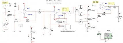
I have ordered two OPA445AP chips (high voltage op-amps with FET inputs so you can plug a guitar on them and use high pots for the tone stacks) - they are arriving today to try things on. They are very expensive, hence I bought just two.
Currently experimenting with TL072/OPA2341 (both FET inputs), supplies at +/-17V with max Av=50 and Rf bypassed with 25 pairs of germanium/schottky diodes. Very similar to Doug's schematic above, which is also found in the Fender Princeton Chorus (at least). The difference is I use the right number of diodes to account for the total voltage of the rails, which is almost the voltage across "Rf", and they are germanium and/or schottky. For 17V supplies you need 120 diodes in total. I have used around 50 as I did not have any more.
I am trying to get the shape out of the array of diodes with no clipping in any stage/op-amp. With +/- 15V supplies it gets quite hard to achieve. Our first try also has quite a "fuzz" sound on the heavy distortion channel so we are experimenting there too.
I also just noticed on the Mesa Boogie Lonestar, a pair of back to back 15V zeners (4744) just before the post-amp stage... Hmmm...
Some of the tests are we are doing are:
1) strum the low strings, hear the distortion (and look at the scope) - how long does it last before it falls back to pure sinusoidal? Ideally it should not, ever revert to sinusoidal. In practice, with the soft-overdrive, probably 2-3 seconds.
2) strum the high strings, repeat test above. Is the time taken before it goes back to sinusoidal exactly the same? If not there is an issue. And we have an issue in that our array of diodes creates a fuzzy sound - caps need to be strategically placed to tame the fuzz unless you like the Jimi Hendrix sound (my son does not so we will probably have a switch "fuzz/deep".
3) do we detect hard clipping anywhere at the output of any op-amp using the scope? If yes then we are driving too hard and must cut down the drive.
4) examine shape of compressed curve. Is it nice and rounded or is it clipped anywhere? Typically that means that at the part of the circuit we have exceeded the supply rails.
Today I will try to compress two channels in sequence so as to stay within the +/-17V supplies, before the new, high volt chips arrive. Although this is not how the Lonestar does it. Looking at its schematic, the first stage multiplies by 50 and does not distort at all under any circumstances (it has no variable gain controls for the first stage so the sound must be totally clean by definition).
It is too soon to publish any circuits as I am experimenting with almost every aspect at the moment and the sound is still not quite right.
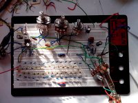
I have transcribed yesterday's circuit from the breadboards and it looks like this.
The first stage was added in a hurry to give us more distortion late last night. Without the first stage we get a "clean" channel that overdrives when the gain is turned over 50%, but it never really distorts too hard.
The tone stack is the usual Fender adjusted to match 100K log pots which I have had handy as well as provide the contour of the Princeton Chorus. The pots should be all audio log.
Attachments
Thanks for posting, otherwise it would have been only a guessing game.
1) it looks good
2) you do *not* need +/-60V Op Amps, 50V RMS, etc.
You are doing fine with what you are showing.
3) with those rails, 20X gain in the first stage is about max you can risk with "normal" pickups.
It will clip with an EMG or a Super Distortion pickup, so I suggest you lower U2a to 10X, to play it safer.
4) you don't need higher rails for U1a
Since the diodes are in the feedback loop (I was not sure about your configuration before), and you have "only diodes" there, no resistors, peak voltage will be peak diode array saturation voltage.
*You* are deciding this, so pull some diodes until you are sure you don't reach rails.
5) you are using a non inverting configuration for U1a, so to that "own" generated signal, you also add signal present at its input (pin 2), so if you put, say, 5V (clean signal by the way) there, those same 5V will present at the output, mixed with the distorted signal.
And I think there is where you have a problem.
A little clean signal mixed with distortion helps clarity, but here it may be overpowering.
Another reason to lower U2a gain.
6) the rest looks fine, with the only small detail you forgot to scale the treble cap, C2, which should be 470pF
7) be realistic as what you are trying to achieve.
You can get a very good sounding SS preamp, which is excellent, but tubes clip in a very different way, totally unlike diode clipping.
You can simulate both and look at the very different waveforms.
In fact, when clipping diodes are introduced in tube amps, such as infamous Marshall's JCM900 (and a few JCM800) sound is later described by Musicians as harsh/brittle/fuzzy/you name it.
Good luck.
Argentina? It must be in the small hours there?
Let me reply :
3) Yes first stage was a quick bolt on very late at night when my son said "what would the distortion channel sound like?". I will need to make sure there is no clipping under normal circumstances. We have 3 electric guitars, two with EMGs , but the old Gibson is still the loudest on its bridge pickup.
However there is not much I can do if someone plugs in various stomp boxes and pedals at the input with the volume knobs to max. This is a major and often overlooked part of a design. You have to draw the line somewhere. You cannot account for everything. Obviously using a tube that can swing to +/-100V at the input certainly helps. We can also add back to back zeners at some arbitrary voltage but that is not soft clipping. Still no substitute for a 200V tube.
This is one of the parts I want to get right - having a +/- 50V chip at the input will certainly help. Shame my bench PSU only goes up to +/-25V.
4) The diode array as you say determines the peak votage, which is more or less the rail voltage (less the capability of the op-amp, less the 2K resistor). Adding more diodes increases this peak voltage and removing diodes decreases it. Using a lot of small voltage drop schotttkies or germaniums helps shape the curve gently, rather than using say a zener which would be abrupt and almost as bad as the op-amp clipping.
In terms of sound quality, removing a few diodes results in clipping earlier, thus producing more distortion. Adding more diodes suppresses the signal more gradually.
My ideal would be to use just enough diodes to suppress 20-30% below max rails level - some peaks would still escape and reach the rails but with the extra headroom it would still not clip.
In the simulation I used a lot of diodes to drop 15 Volts in either direction. In the actual breadboard I ran out of diodes and used a combination of germanium and schottkies, 26 in each direction, keeping the signal from clipping just under 8-9V with max rails at 17V.
5) I am not sure I understand that. Are you saying that stray capacitances around U1 will feedback distorted singal from pin 1 (out) and 2 (Vin-) back to pin 3 (Vin+) and thus create some sort of unwanted positive feedback? I will try to make U1 an invering amp to see if it makes a difference.
6) for the treble cap I checked with the scope at 50Hz and 5000Hz - I tried to equalise the treble with the bass when the respective pots are turned to max. Around 220pf gave me same treble as bass. I used the ToneStackCalculator for initial design trying to copy the Fender Princeton's curves. I decided that the Mesa Boogie's Lonestar stack is not good, and looked at the Princeton Chorus stack, with uses 50K pots and achieves much more bass, so on the tonestackcalculator I tried to match the curve of that. It still is not good, too little bass, treble is OK. Very subjective matter BTW.
However, my son's friend buight an Egnater valve amp head, and while he was playing I was messing with the clean channel's tone controls, and believe me I could not hear a difference with the treble past 12 o'clock.
7) the whole idea behind it is this - and I may be very wrong.
a) there is a difference in the tone with amplifying the guitar singal by 50 with a tube without clipping, then tapping 1/10, resulting in a mathematical "Av=5" and with simply amplifying by 5 in an op-amp.
b) if I amplify by 50 and get a 50V pk swing, then use 400 germanium diodes to "shape" this signal (saturation at 100V), I will emulate the tube which also clips at 100V and plays with maybe 1% distortion at 50V.
But I may be very wrong.
No,I do not speak about signal feedthrough or parasitics, I speak about having at the output (and in phase) *any and all* signals present at the +input.5) I am not sure I understand that. Are you saying that stray capacitances around U1 will feedback distorted singal from pin 1 (out) and 2 (Vin-) back to pin 3 (Vin+) and thus create some sort of unwanted positive feedback? I will try to make U1 an invering amp to see if it makes a difference.
Even if you short the diodes , you still have the full input signal at the output.
That does not happen in an inverting amp
Yes indeed. For guitar preamps, "flat" is "bassy".6) for the treble cap I checked with the scope at 50Hz and 5000Hz - I tried to equalise the treble with the bass when the respective pots are turned to max. Around 220pf gave me same treble as bass. I used the ToneStackCalculator for initial design trying to copy the Fender Princeton's curves. I decided that the Mesa Boogie's Lonestar stack is not good, and looked at the Princeton Chorus stack, with uses 50K pots and achieves much more bass, so on the tonestackcalculator I tried to match the curve of that. It still is not good, too little bass, treble is OK. Very subjective matter BTW.
Marshall type EQ uses a linear pot there, Fender type a special Log with 30% centerpoint, instead of the usual 10% , so unless you use the special pot, it's either "too slow" or "too fast".However, my son's friend buight an Egnater valve amp head, and while he was playing I was messing with the clean channel's tone controls, and believe me I could not hear a difference with the treble past 12 o'clock.
Yes, there is, but not *that* large, the op amp signal will be very clean, the tube will have, say, 1 or 2% distortion, quite soft.7) the whole idea behind it is this - and I may be very wrong.
a) there is a difference in the tone with amplifying the guitar singal by 50 with a tube without clipping, then tapping 1/10, resulting in a mathematical "Av=5" and with simply amplifying by 5 in an op-amp.
Maybe they start clipping at the same level, if you choose the proper amount of diodes, but beyond clipping waveform will be very different.b) if I amplify by 50 and get a 50V pk swing, then use 400 germanium diodes to "shape" this signal (saturation at 100V), I will emulate the tube which also clips at 100V and plays with maybe 1% distortion at 50V.
So the first change is to make the amps inverting so that the input signal does not appear at the output, especially if the output is "modified". Had never thought about that before, thank you.
The second problem is to find a bench PSU for +/-45V... Not an easy task and am a bit cautious to breadboard straight out of a +/-45V supply without any current limiting. And the two OPA445 chips are beckoning...
The third item would be to find a way to pack 100 or 400 diodes on a breadboard and run more tests.
I will post comments/schematics/results as soon as possible.
You might find these two threads on a different forum of interest.
Triode Emulation X-Y plots
Look Ma, NO POTS!
I think you have to join the forum to see the attachments.
Triode Emulation X-Y plots
Look Ma, NO POTS!
I think you have to join the forum to see the attachments.
I see your diode block is general and not detailed, but it looks familiar. Someone has already mentioned the inverting idea, and I've done that too. I posted an LTSpice schematic with a bunch of diodes here in post #18 (remove the .txt file extension, and load it in LTSpice, a free simulator program):
http://www.diyaudio.com/forums/inst...tortion-transistors-op-amp-feedback-loop.html
Also, it may be cheaper and faster to simulate this in LTSpice than to keep making circuits. LTspice also has a neat feature I've never used (haven't looked into exactly how it;s done), you can send a .wav file into a circuit and generate a .wav file from a circuit's output. I've made this circuit and the output has a big dynamic range, both in distortion type and in volume, and in that respect it's "better" than tube distortion. I use 1n914/1n4148's with their usual 0.6V drop, but I've considered using germanium or Shottky diodes for the same reasons as you, to get more diode drops per volt of signal.
One of the things I've wanted to do with that circuit is make it with the diodes in a single direction instead of both, and make two of the circuits cascaded with an attenuator in between so the distortion given to the positive and negative parts of the wave can be varied independently.
You might find these two threads on a different forum of interest.
Triode Emulation X-Y plots
Look Ma, NO POTS!
I think you have to join the forum to see the attachments.
Just from the first post it seems this guy was reading my mind! I had the idea of using dozens of diodes to chip away little pieces of the curve at a time way back, honest!
I am also of the opinion that a "passive" diode array would be better than clever tricks with "active" op-amps or transistors in the feedback loop.
Having said that, I recently spent a lot of time on a wien bridge oscillator using diodes and then FETs in the feedback loop (FETs being less temperature sensitive). I was testing with a 3KW fan heater heating up the circuit to 70-80C and trying to get a stable waveform (amplitude). The original design (HP comes to mind) used a light bulb.
So I acknowledge there is a lot one can do in the feedback loop, so am now registering and ready to read (and learn) more.
I see your diode block is general and not detailed, but it looks familiar. Someone has already mentioned the inverting idea, and I've done that too. I posted an LTSpice schematic with a bunch of diodes here in post #18 (remove the .txt file extension, and load it in LTSpice, a free simulator program):
http://www.diyaudio.com/forums/inst...tortion-transistors-op-amp-feedback-loop.html
Also, it may be cheaper and faster to simulate this in LTSpice than to keep making circuits. LTspice also has a neat feature I've never used (haven't looked into exactly how it;s done), you can send a .wav file into a circuit and generate a .wav file from a circuit's output. I've made this circuit and the output has a big dynamic range, both in distortion type and in volume, and in that respect it's "better" than tube distortion. I use 1n914/1n4148's with their usual 0.6V drop, but I've considered using germanium or Shottky diodes for the same reasons as you, to get more diode drops per volt of signal.
One of the things I've wanted to do with that circuit is make it with the diodes in a single direction instead of both, and make two of the circuits cascaded with an attenuator in between so the distortion given to the positive and negative parts of the wave can be varied independently.
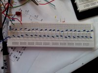
Diodes are an array of between 52 and 80 in the feedback loop depending on what I had in my drawer and how bored I was trying to connect so many together.
For simulation I use NI Multisim version 12. Listening tests are a must, and the curves on the scope after distortion and filtering are nothing to do with the simulation.
I believe that to get a smooth distortion you need to "bend" the curve slowly and incrementally. Otherwise you might as well let the op-amp clip due to its output protection circuitry or because it has reached close to the rails.
This means that the feedback circuit has to be such that it will not activate the op-amp's various protections or limiters in anyway. Some op-amps are much better than others in driving higher loads at full range. I think we did detect an audible difference between the TL072 and the OPA2134 but I cannot say categorically. I am however sticking with the OPA2134.
I attach some pictures to liven up this thread
Attachments
Though I have not read every word of the thread, it seems to me there is one major mis-requirement and that is to assume that you need high voltages to reproduce clipping or even your "chipping away" at a waveform. You can always amplify whatever shape it is you reproduce and it is not necessary for you to push an op amp into clipping to get that part of it. In fact, an op amp is about the last thing you should think of using to reproduce clipping since they have huge open loop gain and will try to correct the errors in a way completely apart from how a standard PA BJT amp would manage with a gain of perhaps 20,000. To do it this way perhaps use an old op amp like the uA741 which has a gain of perhaps 100,000 (still greater than most power amps). Or perhaps set up a 'dummy' push pull stage with low rail voltages and throw in some capacitors to slow it down.
Which brings me to the next thing, that whatever shape you create can always be amplified, meaning that you can have the sound you are after at any level. Although, of course, this is not what actually happens (or happened) with those old guitar valve amps, so some authenticity will be lost without the actual output level, it does mean that you don't need a 200m "no go" area around you to experience the effect. To get this right your actual power amp must be unimpeachable up to these levels.
Personally I would look at this theoretically to see what what the harmonic spectrum is for a clipping guitar amp. This can be done and people like Yamaha will have detailed data of what goes on - you will, after all - only be reproducing one potential instrument out of all those they have researched and incorporated into their synthesisers or other instruments. Where I would start is looking at the content of harmonics that arise with straightforward clipping - ie. taking a straight slice off the top of a sine wave. I don't know whether this stays in identical proportions (though not quantity) the more of a slice you take, but my first suspicion is that's likely. Then I would look at how differently valve amps do this (though why you want a valve sound rather than something new - and don't want to use valves - I don't know). These will be directly mimicable with capacitors and resistors in various places because we know they can be modelled. (Incidentally, use LTspice, get some valve models and you can probably match the output waveform to a pretty close degree of accuracy.)
Also I would concern myself with how the power amp drives your speaker(s). This will have a very important effect on the sound. Valve amps have much higher output impedances, sometimes several ohms, and they don't do it quite the same way. You can do it with just a high powered resistor in series but personally I would do it with some degree of current drive (which will still require at least a wirewound R). I wouldn't be in the least bit surprised if this is the part that you feel is missing in what you have got and that you are much closer than you think. Series resistors do all sorts of nice things like extending the frequency response of a driver upwards in a very natural way and reducing distortion due to changes in parameters in the driver. Current drive does much the same thing, and more so, though will change the frequency response quite a lot since, when done fully, your response will then be changed by a function of the impedance response of the speaker. Generally this is not a great idea at low frequencies where the LF resonance can show up in its full glory, which may be 5x the normal output. The answer to how much you can bear in your application is to have a variable resistor in that bit of the feedback circuit. (It may not be easy to find a sub 10 ohm variable resistor if you are doing it on the output but the same thing can be done with larger values earlier on, but with added complexity. At least I think so.)
Finally, may I mention that the course you are on is in fact much the same as the course that most of us audiophiles have been on for a while, even though you may think you just want the solution to a particular problem. Finding 'that sound' that satisfies us is an almost universal quest; whether as a musician, an instrument maker (you) or a hi fi designer. It is a noble quest and you'd be surprised how much the solutions all end up in the same places.
Last edited:
- Status
- This old topic is closed. If you want to reopen this topic, contact a moderator using the "Report Post" button.
- Home
- Amplifiers
- Chip Amps
- Wider output range from op-amp