I had my dual mono pcbs fulled loaded with components and tested with light bulb attenuator a month or so ago and then I got swamped with work.
I've since scavenged some heatsinks and made a breadboard with a back to temporarily house everything.
I got the four pcbs screwed down and wired. Plugged it in and blew the fuse. Probably should have used the light bulb but they worked when I put it away.
Tonight I've taken it all apart, and without the amp boards connected the psus check out. 20v secondaries, 26v rectified. Blue LEDs light up. With the amp boards connected, the light bulb attenuator glows bright with 60w lamp in it.
I can't figure out where the amp boards are shorted. I've even removed one of them from the heatsink (although the heatsink is not grounded since it's a wooden case.)
I'm posting pictures of one of the amp boards. I can post pictures of the psus if I need to, but they seem to be checking out okay.
Any thoughts appreciated.
Also, when the amplifier board is connected to psu the voltage measure from v+ to pg+ is only about 1.5v if that helps narrow it down. I can't remember what it was like when the amp was working so I don't know if that's normal, but I'm pretty sure not. The power indicator led on the PSU board does turn on briefly and then drops down to a very low glow with the amp board connected.
I'm assuming that something is shorted because after I blew a fuse plugging it in, I started using a "light bulb attenuator" to power it up. The light bulb glows brightly. Both amplifier pcbs have the same condition so far as I can tell. Both PSU pcbs seem to be fine (I can power them up, the light bulb attenuator does not stay lit, the power on led in the circuit glows brightly and the rectified DC voltage measures 26v which sounds right for 20v from the xformer secondaries.)
As I said, the chasis is a temporary setup made of plywood, so the heatsinks can't be grounding significantly to the chasis. Also, I removed one of the heatsinks to test that condition and still see a short as indicated by the light bulb attenuator.
Yes, two amp PCBs, to PSU PCBs and two transformers.
1) *please* even if *you* know red is -V and black is +V could you rewire them the conventional way?
It's needlessly distracting.
2) if both Power amps are fed from the same PSU and one of the chips is shorted, you'll measure a very low residual voltage like you do now.
An actual short might measure 0V or at most a few millivolts, depending on conductor resistance, but getting around 0.7 or 1.4V usually means there is one or 2 diode junctions involved, typical of dead semiconductors.
So your measurement hints at dead chipamps ... or an upside-down powered one.
I removed one of the ICs and light bulb indicator is still glowing. Removing the chip made a bit of a mess of flux, but I checked and there doesn't seem to be any continuity through it so...?
Yeah, I've fixed the wire color for v+ and v-. v+ is now red. I've mostly been doing AC stuff some of which is four wire, so I think my tired brain was in 3 color mode when it came up with the idea.
There are two separate PSU boards, one for each amplifier board. Also two transformers. It IS dual mono so far as I understand the term, thanks.
I'm currently only working with one amp/PSU combo trying to determine what the heck is wrong (the other channel will not be connected to power at all until I get the first channel working.)
BUT another clue hopefully... measuring from pg+ to v+ is around 26v while measuring from v- to v+ is around 20v. Shouldn't it be close to 0v from v- to v+?
Also, the light bulb attenuator does not glow when only v+ and v- are connected. It is only when all four wires v+ pg+ v- pg- are connected that there is a problem (one ground can be connected but not both.)
Thanks for everyone's help! It's always really frustrating when you think you have something working and then come back to it and discover that it isn't working.
Is that when amp not connected?measuring from pg+ to v+ is around 26v while measuring from v- to v+ is around 20v. Shouldn't it be close to 0v from v- to v+?
From V+ to V- it should be 26v+26v=52v
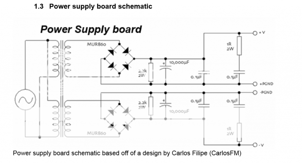
Please post here the PSU schematic.
I remember it uses a dual (independent) secondary transformer and independent bridges (which by the way forbid you to use a regular center tapped transformer) but I don't remember by heart what "pg" means.
An image is worth 1000 words")
I'm quite sure there's some stupid wiring error, the one you look 1000 times and don't "see".
At least it's happened *me* 1000 times and always somebody else asks "shouldn't this wire be there"? or something similar.
So please post the schematic and 2 pictures, one above; one below.
Thanks.
I remember it uses a dual (independent) secondary transformer and independent bridges (which by the way forbid you to use a regular center tapped transformer) but I don't remember by heart what "pg" means.
An image is worth 1000 words
I'm quite sure there's some stupid wiring error, the one you look 1000 times and don't "see".
At least it's happened *me* 1000 times and always somebody else asks "shouldn't this wire be there"? or something similar.
So please post the schematic and 2 pictures, one above; one below.
Thanks.
Now that the only things left on the board are passive devices that are more resilient against over(insert noun here), if you have a thermometer (thermocouple or infrared), you can calculate the amount of power flowing onto the PCB (either by measuring voltage @ transformer after the light bulb, or ammeter... ammeter makes sense...), and if it's large enough all this power would be heating up something somewhere on the board.
Or you can just wait for the resistors to glow or the capacitors to release gas.
Or you can just wait for the resistors to glow or the capacitors to release gas.
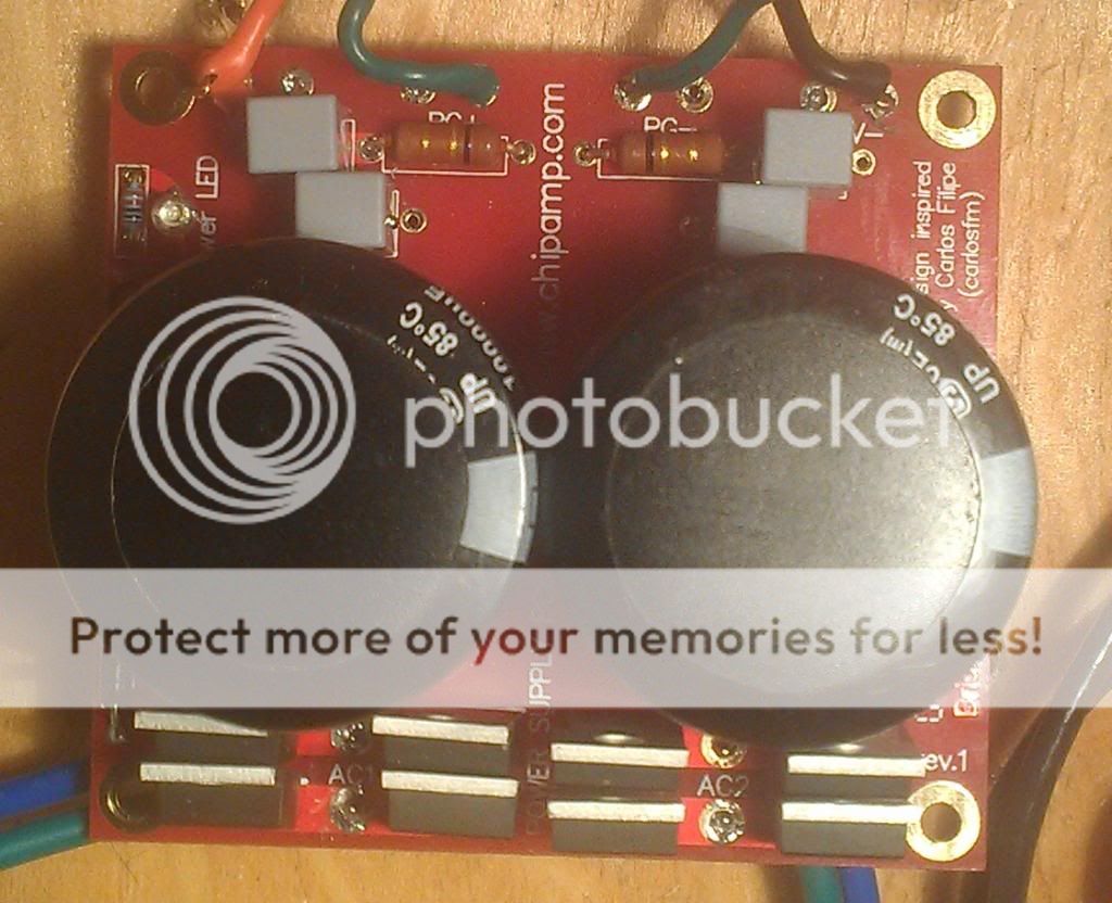
Here is the schematic:
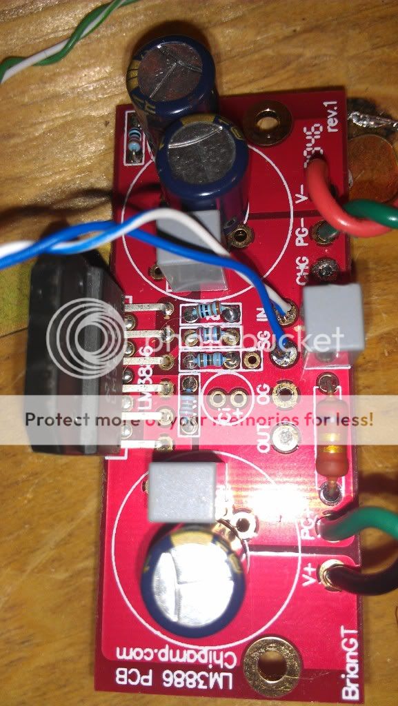
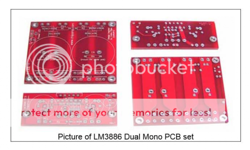
Here is a picture of the PCBs, the larger board is the psu, the smaller the amp
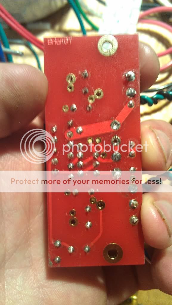
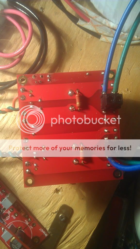
Here is the top of my board:
and the bottom
The transformers are antek an-2220
http://www.antekinc.com/pdf/AN-2220.pdf
I really appreciate the help!
Unfortunately I'm not sure where the thermometer lead for my DMM is right now, and I'd rather not burn stuff up, but if it comes to that...
Here is a picture of the PCBs, the larger board is the psu, the smaller the amp
Here is the top of my board:
and the bottom
The transformers are antek an-2220
http://www.antekinc.com/pdf/AN-2220.pdf
I really appreciate the help!
Unfortunately I'm not sure where the thermometer lead for my DMM is right now, and I'd rather not burn stuff up, but if it comes to that...
- Status
- This old topic is closed. If you want to reopen this topic, contact a moderator using the "Report Post" button.
- Home
- Amplifiers
- Chip Amps
- trouble with BrianGT chipamp lm3886