Hello everyone,
My chipamp (LM3886 x 2 + LM4780 (sub)) has been going strong for about a year now. I've always had a few quirks with it though. I ran out of wire when I did the initial build so I used some really old cheap and nasty unshielded twisted pair wire for the signal. Probably not the best of ideas. I've also been getting a little buzzing on high frequencies on one of the channels.
So I bought some wire from Markertek. I got some good quality Mogami stuff and I am going to rewire the parts I skimped on.
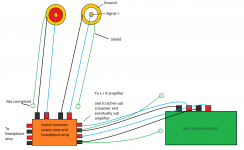
My question is: For each wire run between different components do you attach the wires shield to ground on just the "input" side. For example, my signal comes from 2 RCA jacks to a 4PDT switch (to headphone amp and to power amp), then to subwoofer crossover board. I run wire from the crossover's INPUT terminals(where I just inserted the wire, not on the crossover's output) to the Left and Right channel amp.
So the main wire runs are RCA --> Switch --> Subwoofer crossover --> Left and Right channel.
If you didn't get what I meant with the input terminals and subwoofer thing, I'm essentially just using the input terminals to splice the wire so that I can have the signal go to the subwoofer board AND to the left and right channel.
Here's a partial drawing. Where do the cable shield grounds get attached?
My chipamp (LM3886 x 2 + LM4780 (sub)) has been going strong for about a year now. I've always had a few quirks with it though. I ran out of wire when I did the initial build so I used some really old cheap and nasty unshielded twisted pair wire for the signal. Probably not the best of ideas. I've also been getting a little buzzing on high frequencies on one of the channels.
So I bought some wire from Markertek. I got some good quality Mogami stuff and I am going to rewire the parts I skimped on.
My question is: For each wire run between different components do you attach the wires shield to ground on just the "input" side. For example, my signal comes from 2 RCA jacks to a 4PDT switch (to headphone amp and to power amp), then to subwoofer crossover board. I run wire from the crossover's INPUT terminals(where I just inserted the wire, not on the crossover's output) to the Left and Right channel amp.
So the main wire runs are RCA --> Switch --> Subwoofer crossover --> Left and Right channel.
If you didn't get what I meant with the input terminals and subwoofer thing, I'm essentially just using the input terminals to splice the wire so that I can have the signal go to the subwoofer board AND to the left and right channel.
Here's a partial drawing. Where do the cable shield grounds get attached?
Attachments
Last edited:
You don't want to connect it at more than one point. I have always connected the shield at the output end but I don't think that it matters greatly.
So the shield itself will only ever get soldered once?
If you have two inner conductors, the shield should be connected at one end only.
Connecting the shield at both ends can result in a nasty ground loop.
Right I understand that if there was one single run. So if I had multiple runs, as in the signal was hooked up to the switch as I said....The shield still should only be at one...
shielding ground
If the input jack is grounded on the chassis and the amp is also grounded on the chassis then right, you shouldn't also have the shielding making a second path. So if you have a switch mid-way, I'd ground the shield at the input jack, but not at the switch and for the leg after the switch I'd ground it at the amp but not at the switch. I'm assuming (I know, I shouldn't assume) the switch will also have its body grounded at the chassis. But if not, then you should ground the switch body to one side or the other. So, everything grounded somewhere but no complete second path, no ground loops.
If the input jack is grounded on the chassis and the amp is also grounded on the chassis then right, you shouldn't also have the shielding making a second path. So if you have a switch mid-way, I'd ground the shield at the input jack, but not at the switch and for the leg after the switch I'd ground it at the amp but not at the switch. I'm assuming (I know, I shouldn't assume) the switch will also have its body grounded at the chassis. But if not, then you should ground the switch body to one side or the other. So, everything grounded somewhere but no complete second path, no ground loops.
You don't want the signal ground connected to the chassis, at the jacks. It should only connect to the input resistor just before the chipamp (from which it should have its own separate conductor to star ground). Otherwise, you've created a large "enclosed loop area" between the signal and signal ground conductors, which would make a very good antenna, for anything from AC hum to RF.
All RCA jacks should be isolated from the chassis, and from any other ground.
Anyway, I would use shielded twisted pair, at least internally, with the shield connected to chassis at one end only (and NOT connected to the signal ground, or any part of the RCA jack).
I don't understand your diagram. If you use isolated jacks (insulated from chassis) as you should, and proper internal grounding, and your cables have only a center conductor plus a shield that doubles as the signal ground, then you would want to connect the shield at both ends, everywhere.
Last edited:
You don't want the signal ground connected to the chassis, at the jacks. It should only connect to the input resistor just before the chipamp (from which it should have its own separate conductor to star ground). Otherwise, you've created a large "enclosed loop area" between the signal and signal ground conductors, which would make a very good antenna, for anything from AC hum to RF.
All RCA jacks should be isolated from the chassis, and from any other ground.
Anyway, I would use shielded twisted pair, at least internally, with the shield connected to chassis at one end only (and NOT connected to the signal ground, or any part of the RCA jack).
I don't understand your diagram. If you use isolated jacks (insulated from chassis) as you should, and proper internal grounding, and your cables have only a center conductor plus a shield that doubles as the signal ground, then you would want to connect the shield at both ends, everywhere.
Sorry for the diagram.
I have a wooden chassis...I know terrible for RF suppression. Right now, I have the shield connected to the signal ground only at the RCA inputs. No metal chassis so yes it is isolated.
Should I do as Keith says but not grounding to earth?
Thanks.
The main thing is that the signal and signal ground should never get separated. The signal ground needs to stay ONLY right next to the signal, all the way from the source output to the input shunt resistor at the first active device in whatever amplifier it goes to.
If the ground connects to anything else along the way, and can also take a different path, that doesn't stay right next to the signal, then the enclosed loop area between the signal and ground will be a big antenna. (Similarly, two untwisted wires, with any gap or space between them, would not be good.)
So your switch should be switching both the signal and the ground, and should connect both to only one source and only one destination at a time.
If the switch connects one or more of the grounds from different amps together, that would not be good.
I would much prefer to use shielded twisted pair. Then the shield is just a shield and should NOT be connected to the signal ground. Then you would connect the shield to chassis ground at one end only, always.
With a shielded cable that has only one single inner conductor and an outer "shield" that is also the signal ground, you should always need to connect the shield at both ends, if everything else is set up correctly. Otherwise you would force the signal ground to find some other route, which would make a large enclosed loop area between signal and ground, which makes a much better hum (and RF) antenna.
Last edited:
The main thing is that the signal and signal ground should never get separated. The signal ground needs to stay ONLY right next to the signal, all the way from the source output to the input shunt resistor at the first active device in whatever amplifier it goes to.
If the ground connects to anything else along the way, and can also take a different path, that doesn't stay right next to the signal, then the enclosed loop area between the signal and ground will be a big antenna. (Similarly, two untwisted wires, with any gap or space between them, would not be good.)
So your switch should be switching both the signal and the ground, and should connect both to only one source and only one destination at a time.
If the switch connects one or more of the grounds from different amps together, that would not be good.
I would much prefer to use shielded twisted pair. Then the shield is just a shield and should NOT be connected to the signal ground. Then you would connect the shield to chassis ground at one end only, always.
With a shielded cable that has only one single inner conductor and an outer "shield" that is also the signal ground, you should always need to connect the shield at both ends, if everything else is set up correctly. Otherwise you would force the signal ground to find some other route, which would make a large enclosed loop area between signal and ground, which makes a much better hum (and RF) antenna.
Alright. So from the switch, I should be making multiple runs? Right now, if you understood my correctly, I make one run to this sub preamp/filter board, and then I just use the input terminal blocks there to go to the left and right channel because it saved wire and the amp isn't that spacious.
But you are proposing that from the switch, I should "branch" out directly from the switch contacts?
Also, I do not have a metal chassis, so I guess I'll just connect signal shield to the third prong on the IEC inlet? I can do that pretty easily. However, this shield should not be attached to signal ground...at all?
---
I also have two potentiometers that I want to hook up using twisted-quad (that has a shield). This should should also get connected to "chassis" ground?
One simple rule is this:
Always connect the shielding at the end wich have the highest impoedance. (At the input of every board)
This ends up in to solder the shielding near the input of the amp-board.
If there is separated signal and power earth on the board, it will need one lead from the earth at the signal input down to the powersupply ground. And another lead from the power-ground on the board down to the same point on the powersupply.
Additional lead fron the ground of the input connectors, and from speaker ground bindingpost. All in a "star" to the point at the powersupply.
Any signal (line-level) wich arte to go out of an amp, should have the shielding solderet at the output connector with a groundlead down to the power supply. This signal cable should NOT have its shielding soldered to the board, but left insulated.
This way I have buildt hiss and humfree amplifiers for quite an amount of years now. Oh yeah, even in unshielded cases.
I ALWAYS keeps PE (The power inlet ground) separated from signal ground.
If this has to be connected anywhere, I would recommend to connect that to the chassis, and then have a 10M resistor in paralell with a 1uF 630V capacitor to the signal ground (Internal power supply ground. Then I would have a switch between the CAP and PE to separate chassisground from signal ground just for the giggles. In some areas it seems as a good idea to have AC coupling between PE and signal ground.
Last edited:
One simple rule is this:
Always connect the shielding at the end wich have the highest impoedance. (At the input of every board)
This ends up in to solder the shielding near the input of the amp-board.
If there is separated signal and power earth on the board, it will need one lead from the earth at the signal input down to the powersupply ground. And another lead from the power-ground on the board down to the same point on the powersupply.
Additional lead fron the ground of the input connectors, and from speaker ground bindingpost. All in a "star" to the point at the powersupply.
Any signal (line-level) wich arte to go out of an amp, should have the shielding solderet at the output connector with a groundlead down to the power supply. This signal cable should NOT have its shielding soldered to the board, but left insulated.
This way I have buildt hiss and humfree amplifiers for quite an amount of years now. Oh yeah, even in unshielded cases.
I ALWAYS keeps PE (The power inlet ground) separated from signal ground.
If this has to be connected anywhere, I would recommend to connect that to the chassis, and then have a 10M resistor in paralell with a 1uF 630V capacitor to the signal ground (Internal power supply ground. Then I would have a switch between the CAP and PE to separate chassisground from signal ground just for the giggles. In some areas it seems as a good idea to have AC coupling between PE and signal ground.
Thanks. I'm having a hard time understanding some parts of your post.
Just still confused where and to what the shielding should be connected.
Here are some notes about my amp:
-Signal and power ground are shared
-Wooden chassis. I do have PE connected to the amp ground (isolated by a CL-60 inrush current limiter). This was a suggestion by another diyaudio member a while back.
- Signal comes from RCA jacks, goes through a switch (which can switch between headphone out or power amp out). If power amp out is chosen, three things need signal. Left channel, right channel, and subwoofer.
I have twisted pair shielded cable. Mogami is the brand. Where should the shield be connected and to what? To the protective earth? To signal ground?
I also have two potentiometers that are connected with long cable runs. I was kind of forced to do it this way because I made some other silly design decisions. I also have quad (four wire) shielded Mogami wire. I was planning on using 3 conductors for each potentiometer. However, I wouldn't be sure where to attach that shield either?
Thank you. I really appreciate the help.
Last edited:
Well your drawing did not show shielded twisted pair! It shows coax, like RCA cable! And it shows the shield as connected to audio signal ground!
If the shield is NOT CONNECTED, ANYWHERE, TO SIGNAL GROUND, then yes, you can connect it to whatever other ground point you want, I suppose. But only the connect the shield at one end of each cable, to ground (BUT NEVER to "signal ground"). And make sure that the shield on the other end is connected to NOTHING.
What kind of connectors are on the ends of your audio cables (the ones you say are shielded twisted pair)?
Just kill me now...
Also, I do not have a metal chassis, so I guess I'll just connect signal shield to the third prong on the IEC inlet?
If the shield is NOT CONNECTED, ANYWHERE, TO SIGNAL GROUND, then yes, you can connect it to whatever other ground point you want, I suppose. But only the connect the shield at one end of each cable, to ground (BUT NEVER to "signal ground"). And make sure that the shield on the other end is connected to NOTHING.
What kind of connectors are on the ends of your audio cables (the ones you say are shielded twisted pair)?
-Signal and power ground are shared
- Signal comes from RCA jacks, goes through a switch (which can switch between headphone out or power amp out). If power amp out is chosen, three things need signal. Left channel, right channel, and subwoofer.
I have twisted pair shielded cable.
Just kill me now...
Well your drawing did not show shielded twisted pair! It shows coax, like RCA cable! And it shows the shield as connected to audio signal ground!
If the shield is NOT CONNECTED, ANYWHERE, TO SIGNAL GROUND, then yes, you can connect it to whatever other ground point you want, I suppose. But only the connect the shield at one end of each cable, to ground (BUT NEVER to "signal ground"). And make sure that the shield on the other end is connected to NOTHING.
What kind of connectors are on the ends of your audio cables (the ones you say are shielded twisted pair)?
Just kill me now...
I take that back. Signal and power are not shared. The amp sounded very good. So please don't say that.
Connectors? What do you mean? RCA?
They are soldered.
For proper shielding the shield should be connected at both ends., connected at one end it is an antenna, and provides no RF shielding. A better method is to either use an isolation transformer, or at least connect the shield through a ring of capacitors at one end instead of leaving it floating.
http://www.hottconsultants.com/pdf_files/Audio Interconnections.pdf
http://www.hottconsultants.com/pdf_files/Audio Interconnections.pdf
For proper shielding the shield should be connected at both ends., connected at one end it is an antenna, and provides no RF shielding. A better method is to either use an isolation transformer, or at least connect the shield through a ring of capacitors at one end instead of leaving it floating.
http://www.hottconsultants.com/pdf_files/Audio Interconnections.pdf
Ugh so many differences in opinions...
- Status
- This old topic is closed. If you want to reopen this topic, contact a moderator using the "Report Post" button.
- Home
- Amplifiers
- Chip Amps
- Wire runs within the chassis. Shielding properly.