Hi,
I am trying to connect 32V DC from a DC-DC boost converter to a LM3886 board which has +ve, -ve and ground on it. But the boost converter has only +ve and -ve outputs.
I currently current use the DC-DC boost converter to power couple of TDA2050 amps. The DC-DC boost converter is power by my PC PSU. I am very satisfied with the quality of the sound, so would like to explore if I can do something similar for the LM3886 board.
Can I try 2 DC-DC boost converters with 32V outputs?
Appreciate any suggestions.
Thanks
Arvind
Last edited:
This is my first post here, but I do have experience building SMPUSs / DC-DC converters.
The answer depends on earthing + grounding of the DC-DC converters / topology inside. If they're isolated then it should be ok. Check there's no ground in to ground out connection, and if not, you can join them in series.
Check resistance both ways with a meter, and diode check as well. Diode check has a higher voltage and will allow you to see the Vf of any protection diode if it doesn't show with a straight resistance check.
You can use the LM3886 in single rail apps, but 32V might be a bit low. See page 6 of TI's datasheet for this.
This is my first post here, but I do have experience building SMPUSs / DC-DC converters.
The answer depends on earthing + grounding of the DC-DC converters / topology inside. If they're isolated then it should be ok. Check there's no ground in to ground out connection, and if not, you can join them in series.
Check resistance both ways with a meter, and diode check as well. Diode check has a higher voltage and will allow you to see the Vf of any protection diode if it doesn't show with a straight resistance check.
You can use the LM3886 in single rail apps, but 32V might be a bit low. See page 6 of TI's datasheet for this.
Thanks TheGabbleDuck, I will give your suggestion a try.
I am thinking of using 2 DC-DC converters each capable of delivering 32V+.
I purchased a preassembled LM3886 kit which takes +ve and -ve supply so I am trying to figure out a way to power the kit with 2 DC-DC converters running off my computer SMPS which has 15V+ 10A.
Last edited:
Thanks TheGabbleDuck, I will give your suggestion a try.
I am thinking of using 2 DC-DC converters each capable of delivering 32V+.
I purchased a preassembled LM3886 kit which takes +ve and -ve supply so I am trying to figure out a way to power the kit with 2 DC-DC converters running off my computer SMPS which has 15V+ 10A.
Hi TheGabbleDuck,
I checked the input ground and output ground they seem to be shorted.
I found a picture that illustrates what I am trying to do from http://kb.bkprecision.com/questions.php?questionid=224. Any ideas?
Attachments
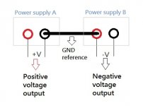
Mmm. I understand what you're trying to do, and with something like a lab / bench PSU as shown above you can do this, as the grounds of the individual power supplies aren't linked - they're "floating".
However, because you're using a boost converter, unfortunately, you won't be able to link the positive of one to the negative of a second, to create a split rail supply. Effectively, you'll be shorting out the "negative" supply, when you try and connect it's positive to the ground rail.
Personally, I would go with a straight rectified non regulated PSU. I've just done this for a pair of LM3886's for a basic stereo amp - sounds good so far. A lot of people don't bother with putting large value reservoir caps in, but I did -10,000uF on each rail. The data sheet says 84V max, but usually it's less with a signal present. I'd use 35V for safety and because that's quoted for 8 ohm output.
So, 35 * .707 = 24.745 = 0-25 0-25 secondary op toroidal transformer required.
Current = 68W into 4ohm = square root of (68 / 4) = 4.1A. Say 5 for ~20% margin, so that works out at (25 * 5) * 2 = 250 - use a 300VA transformer for some margin here.
So, use a 5 - 10A bridge rectifier, find 2 pairs of 4700uF electrolytics - 2 in parallel for positive and negative rails, and that's pretty much adequate. Just looked on Farnell, and bits cost less than £50 for the above specification.
Mmm. I understand what you're trying to do, and with something like a lab / bench PSU as shown above you can do this, as the grounds of the individual power supplies aren't linked - they're "floating".
However, because you're using a boost converter, unfortunately, you won't be able to link the positive of one to the negative of a second, to create a split rail supply. Effectively, you'll be shorting out the "negative" supply, when you try and connect it's positive to the ground rail.
Personally, I would go with a straight rectified non regulated PSU. I've just done this for a pair of LM3886's for a basic stereo amp - sounds good so far. A lot of people don't bother with putting large value reservoir caps in, but I did -10,000uF on each rail. The data sheet says 84V max, but usually it's less with a signal present. I'd use 35V for safety and because that's quoted for 8 ohm output.
So, 35 * .707 = 24.745 = 0-25 0-25 secondary op toroidal transformer required.
Current = 68W into 4ohm = square root of (68 / 4) = 4.1A. Say 5 for ~20% margin, so that works out at (25 * 5) * 2 = 250 - use a 300VA transformer for some margin here.
So, use a 5 - 10A bridge rectifier, find 2 pairs of 4700uF electrolytics - 2 in parallel for positive and negative rails, and that's pretty much adequate. Just looked on Farnell, and bits cost less than £50 for the above specification.
Thanks. One last question before I drop this idea - if I use 2 separate switching supplies (like in they are connected to 2 separate wall sockets) which are then connected to 2 separate dc-dc converter can I do what is shown in the above figure? I am trying to use this exercise to understand the concept of -ve potential.
Thanks again for taking time to explain.
I just checked earthing and ground connections on an ATX PSU I have in bits here.
Unfortunately, the answer is still no. Negative on the ATX PSU is connected to the metal case, and to earth. This means the negative on each booster PSU is at the same potential, linked at the socket outlet earth, which then obviously means you'd short out the negative rail.
As for understanding the concept of -ve potential, it's only relative. In this case, relative to ground. You could also maybe view it as 0v, 35V and 70V, with the 35V rail earthed / used as ground. That confuses the issue a bit though. For audio purposes, we want to make a speaker diaphragm move forwards and backwards. So, it rests in the centre, with no power applied. Put voltage across one way and it moves out, voltage across it the other way round and it moves back from its rest position.
So, the split rail PSU lends itself very well to being able to supply both positive and negative voltage at the output. Otherwise, you need a dirty great output capacitor to achieve the same thing, with a single rail supply. Then you need an input capacitor to block DC, then you need biasing to keep the amp at 50% V+ level, and so on.
This is a very basic explanation, and analogue circuitry isn't my strong point, but I hope the above is useful.")
Something I might suggest is building the PSU in a modular / separate box, then you can use it on multiple amp builds without having to take it apart. Look up star grounding and read about good wiring practice for audio amps, and have fun building / learning. I'm finding it good fun getting back into analogue after years of MCUs and digital PCB design!
Unfortunately, the answer is still no. Negative on the ATX PSU is connected to the metal case, and to earth. This means the negative on each booster PSU is at the same potential, linked at the socket outlet earth, which then obviously means you'd short out the negative rail.
As for understanding the concept of -ve potential, it's only relative. In this case, relative to ground. You could also maybe view it as 0v, 35V and 70V, with the 35V rail earthed / used as ground. That confuses the issue a bit though. For audio purposes, we want to make a speaker diaphragm move forwards and backwards. So, it rests in the centre, with no power applied. Put voltage across one way and it moves out, voltage across it the other way round and it moves back from its rest position.
So, the split rail PSU lends itself very well to being able to supply both positive and negative voltage at the output. Otherwise, you need a dirty great output capacitor to achieve the same thing, with a single rail supply. Then you need an input capacitor to block DC, then you need biasing to keep the amp at 50% V+ level, and so on.
This is a very basic explanation, and analogue circuitry isn't my strong point, but I hope the above is useful.
Something I might suggest is building the PSU in a modular / separate box, then you can use it on multiple amp builds without having to take it apart. Look up star grounding and read about good wiring practice for audio amps, and have fun building / learning. I'm finding it good fun getting back into analogue after years of MCUs and digital PCB design!
I just checked earthing and ground connections on an ATX PSU I have in bits here.
Unfortunately, the answer is still no. Negative on the ATX PSU is connected to the metal case, and to earth. This means the negative on each booster PSU is at the same potential, linked at the socket outlet earth, which then obviously means you'd short out the negative rail.
As for understanding the concept of -ve potential, it's only relative. In this case, relative to ground. You could also maybe view it as 0v, 35V and 70V, with the 35V rail earthed / used as ground. That confuses the issue a bit though. For audio purposes, we want to make a speaker diaphragm move forwards and backwards. So, it rests in the centre, with no power applied. Put voltage across one way and it moves out, voltage across it the other way round and it moves back from its rest position.
So, the split rail PSU lends itself very well to being able to supply both positive and negative voltage at the output. Otherwise, you need a dirty great output capacitor to achieve the same thing, with a single rail supply. Then you need an input capacitor to block DC, then you need biasing to keep the amp at 50% V+ level, and so on.
This is a very basic explanation, and analogue circuitry isn't my strong point, but I hope the above is useful.
Something I might suggest is building the PSU in a modular / separate box, then you can use it on multiple amp builds without having to take it apart. Look up star grounding and read about good wiring practice for audio amps, and have fun building / learning. I'm finding it good fun getting back into analogue after years of MCUs and digital PCB design!
Thank you. It was a nice learning exercise for me, without actually blowing up something
Ok, thought this may help somebody.
I have my LM3886s running from 2 AC adapters (wall warts) supply 12V (5A). As TheGabbleDuck pointed I could not use my computer PSU but 2 independent AC adapters did the trick. I boosted 12V using DC boost converter to +35V and -35V to power the LM3886s. The 2 ac adapters have no 3rd earth pin (only 2 pins). By connecting the +ve of one dc boost to -ve of another and using this point as my ground for my amp I was able to run the LM3886s just like the image in my earlier post.
I have my LM3886s running from 2 AC adapters (wall warts) supply 12V (5A). As TheGabbleDuck pointed I could not use my computer PSU but 2 independent AC adapters did the trick. I boosted 12V using DC boost converter to +35V and -35V to power the LM3886s. The 2 ac adapters have no 3rd earth pin (only 2 pins). By connecting the +ve of one dc boost to -ve of another and using this point as my ground for my amp I was able to run the LM3886s just like the image in my earlier post.
Last edited:
- Status
- This old topic is closed. If you want to reopen this topic, contact a moderator using the "Report Post" button.
- Home
- Amplifiers
- Chip Amps
- Can I connect DC boost PSU to LM3886 ?