Well, nobody mentioned "high frequency " ")
Anyway, don't worry; most are guaranteed full precision up to 400 or 440Hz , check the manual, and at 1KHz they are reasonably close.
Of course, at 10 or 20 KHz most can't be trusted at all, but there are other methods, an "RF Probe", built with 1 diode, 1 capacitor and 1 resistor is usable and flat, as the name says, up to many Mega Hertz, how's that? .
Anyway, don't worry; most are guaranteed full precision up to 400 or 440Hz , check the manual, and at 1KHz they are reasonably close.
Of course, at 10 or 20 KHz most can't be trusted at all, but there are other methods, an "RF Probe", built with 1 diode, 1 capacitor and 1 resistor is usable and flat, as the name says, up to many Mega Hertz, how's that?
.Yes, of course.
And some can reach quite high, it depends on what the designer used as a full wave rectifier.
But anyway I suggest you build the RF probe.
Untitled Document
And some can reach quite high, it depends on what the designer used as a full wave rectifier.
But anyway I suggest you build the RF probe.
Untitled Document
problem is solved... unfortunately, because it can't be solved completely. i reversed the input from the soundcard when the sound appeared to be panned awkwardly and IT is the main problem (beside the volume pot on the amp). i "pimped" it by removing some smoothing / frequency limiting caps and the effect (also tilting the balance by software) seems to be more limited.
Still happy about solving the mistery i played the amp with the volume at 5% for about 1 hour then had to stop because the now sharper highs felt like pressing really hard on my head to where it got painful
Oh, also replaced all paper caps with polypropilene, they seem slightly nicer.
Thanks for all the help!
since it's still related to the same amp i'm gonna keep posting here, at least until an admin gets tired of this and locks the topic.
i eliminated the previous power supply as it seemed to sag when pushing the amp close to 1/3 of it's power. now using one double U-core transformer 2x14Vac for output stage (LM3886) and a "classic" E+I core for the preamp 6,3Vac+300Vac+30Vac.
There is a slight hum apparently 50Hz the network frequency that wasn't there before independent of the volume potentiometer. It is only audible with my ear stuck to the test speaker. What i did:
1. rearranged rectifier bridge for the output stage thinking the doubler scheme i was using had insufficient filtering. now with classic rectifier bridge + 2x4700uF per rail the hum is very much the same and frequency has not changed (so it's not bad filtering).
2. removed tubes from sockets and disconnected the heater wires (thinking they would bring in AC somehow into the signal). still the same.
3. i disconnected the preamp transformer completely as it was also audibly humming in an annoying fashion. now the amp casing no longer hums but the slight hum in the speaker stays the same.
4. moved the remaining transformer around as it's not fixed yet to the case (just sits on rubber legs) still there is absolutely no change in the hum level.
There no ground loops i can see but... i must be doing something wrong
Can you provide measurements on the hum at the speaker leads? A sensitive AC VM is fine...In my experience, 1 mV is clearly audible, 0.1 mV is typically inaudible. It does depend, also, on the spectrum of the hum, the quietness of the room, the sensitivity of the speakers, and the acuity of your hearing!
It seems like you're doing the right thing...a divide and conquer approach to find the source of the hum. Schematics and pictures might help the remote troubleshooting procedure.
Akitika GT-101
It seems like you're doing the right thing...a divide and conquer approach to find the source of the hum. Schematics and pictures might help the remote troubleshooting procedure.
Akitika GT-101
Is your AC input wire pair tightly twisted, everywhere? What about the pairs from the transformer secondaries? And they should all be far away from any low-level or signal conductors and components, or at a right angle to them.
Check your input signal and input signal ground conductors again. They are either twisted or shielded, and signal ground is not connected to anything until it's on the amp board. Input jacks are isolated/insulated from chassis. There is a separate connection to star ground from signal ground on amp board. Signal and signal ground traces stay very close to each other everywhere, on amp board.
There should be sufficiently-large electrolytic decoupling capacitors near amp power pins.
Last edited:
Yes and no... the lowest scale for AC on this meter is 2V, not very precise. The reading fluctuates sometimes even though the speaker hum does not change. So much for accuracy. It says between 1-3mV with speaker connected, 5mV straight if there's no speaker. Won't that include the error because of the LM's offset? (keep in mind these are not original ic's). It's barely audible in quiet conditions if i keep speaker 10cm from ear however with my regular use speakers that have higher sensitivity and most importantly they have enclosures, it just may be audible from 1-2 meter distance.
Yes gootee there is a main star ground in the middle of 2 of the large capacitors in the power source. The preamp having different power supply has it's own star and since there has to be the same potential of the signal and power ground, there is a wire uniting them.
Solved part of the problem removing small resistor that connected signal gnd with main gnd in the output stage. Was not needed anyway since they come together elsewhere. Also on twin shielded cables carying audio only one shield connected at both ends, also helped diminish hum a little.
No... eager to test the thing i did not twist anything except the wires for tube heaters. I'll do that this evening to see if it kills the hum. Makes sense as there's AC going from back to front whre the switch is then back to the transformers... a long path.
** hum apparently doesn't register on the frequency counter perhaps it's too weak or in spite what i'm hearing it may not be a single clean frequency
Last edited:
gootee if i pull the plug the hum stops instantly, there remains just the very small hiss that is normal, until the capacitors in the power supply discharge. i noticed also when connecting both transformers the hum is modified. if the primary windings are in phase the hum is still 50Hz just louder than with only the main transformer. if the windings are in anti-phase the hum is not so loud but becomes 100Hz (by "ear-meter").
JMFahey, no, actually it should be 220V. in reality it's 230 on a good day when there is a lot of load. usually it sits at 247V (possibly 250V at night). that's why this is odd. if the earth was still earth, there should be 200-and-something volts between it and the power line. instead it sits about in the middle.
JMFahey, no, actually it should be 220V. in reality it's 230 on a good day when there is a lot of load. usually it sits at 247V (possibly 250V at night). that's why this is odd. if the earth was still earth, there should be 200-and-something volts between it and the power line. instead it sits about in the middle.
JMFahey, no, actually it should be 220V. in reality it's 230 on a good day when there is a lot of load. usually it sits at 247V (possibly 250V at night). that's why this is odd. if the earth was still earth, there should be 200-and-something volts between it and the power line. instead it sits about in the middle.
OK, now that clears things up.
You do NOT have "220V/neutral" available on your (formerly 220V round pin ) wall socket but you inherited an *old* home power distribution system, once somewhat popular: 2 x 110V out of phase lines, none of which is ground.
What's grounded is the center tap of the 110V+110V distribution transformer which powers a few blocks in your neighbourhood.
I *guess* it was chosen for safety: appliances "see" 220V, but no line is more than 110V away from Earth.
Best of both Worlds ... except it's murder on hum sensitive Audio stuff.
I used to live in a house wired like that
Had to get my own ground using a 3 Meter long Aluminum bar, making a hole in a patio until I found real, black humid Earth.
Oh well.
What you measure is quite reasonable: both voltages add up to about 230V, the new European "de facto" midrange between 220 and 240V standards, and are not symmetrical because of uneven load.
And rising to 250V when unloaded at some times of the day is reasonable too, old overworked transformers and lines have poor regulation.
So, given that you have to live with it, simply remember no power pin is "neutral".
Unless you make a *big* 220V/220V transformer, primary across both "live" lines, secondary ground and hot 220V.
I was about to do the same at my old home, but then moved to a "normal" wired house, so it was not necessary.
Still have the huge transformer core and the heavy duty 5 position switch (since I was getting into it anyway), I was going to add 5 taps to fine tune wall voltage at home.
The main problem is that IT is not the problem... therefor i'm at a loss what might be. I found on the hallway an outlet with normal 220V-0V output and grounding but nothing changed. Since this apartment building is awkwardly wired, at the midpoint between 2 transformers, some outlets are wired to the old transformer, some to the newer one, that was needed only in recent years with more and more appliances drawing power.
There is no noise from the preamp. I've powered it up and it's dead silent regardless of potentiometer position. There's just the everpresent hum from the output stage. I could probably live with it as it's inaudible when say the computer is running (where it gets it's audio anyway) but it's just a mystery to me what could be happening.
There is no noise from the preamp. I've powered it up and it's dead silent regardless of potentiometer position. There's just the everpresent hum from the output stage. I could probably live with it as it's inaudible when say the computer is running (where it gets it's audio anyway) but it's just a mystery to me what could be happening.
So then your problem is probably something covered in post 28.
Your signal input and signal ground reference conductors (or paths, or partial paths) might have space between them, allowing them to be an antenna for hum.
Otherwise, maybe your signal reference ground at amplifier input is bouncing. Possibly you connected it too close to rectifier in PSU, instead of after the smoothing caps?
Otherwise, maybe your smoothing caps are not doing a good-enough job and your amp's PSRR is terrible? Do you not have any global negative feedback?
Otherwise, maybe your speaker wires have space between them, and are acting as an antenna.
A picture of the amplifier circuits would be helpful.
Last edited:
while i'm gonna look for a decently priced scope online, i'll try moving the earth point to different places in the ground path. perhaps it would become quiet if i put it on the signal ground instead.
when building it i considered the following layout i found on the net (seems very revealing):
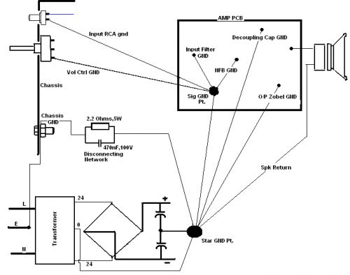
Otherwise the schematic remains pretty much as previously posted by me, just the LM3886 now uses split power supply.
there could be a potential problem indeed that cables to the output connector pass close to the main transformer. i can imagine how signal induced in the output cable would go to the LM's input through the feedback resistor. if all else fails i'll dislodge the connector and place it elsewhere.
when building it i considered the following layout i found on the net (seems very revealing):
Otherwise the schematic remains pretty much as previously posted by me, just the LM3886 now uses split power supply.
there could be a potential problem indeed that cables to the output connector pass close to the main transformer. i can imagine how signal induced in the output cable would go to the LM's input through the feedback resistor. if all else fails i'll dislodge the connector and place it elsewhere.
- Status
- This old topic is closed. If you want to reopen this topic, contact a moderator using the "Report Post" button.
- Home
- Amplifiers
- Chip Amps
- Practical considerations building LM3886 amp