Hi Folks,
sorry for asking (i tried searching the forum ).
).
Can anyone please post a schematic or a link to a GainClone circuit which works in non-inverted mode and uses a LM3875 and 47K pot (this is what i have here...)
Lots of schematics can be found on the www but only a few of them are made based on the experiences you folks made. Unfortunately i can not judge which circuits out there are the good ones ...
...
Thanks in advance
Cheers
Christian.
sorry for asking (i tried searching the forum
).Can anyone please post a schematic or a link to a GainClone circuit which works in non-inverted mode and uses a LM3875 and 47K pot (this is what i have here...)
Lots of schematics can be found on the www but only a few of them are made based on the experiences you folks made. Unfortunately i can not judge which circuits out there are the good ones
...Thanks in advance
Cheers
Christian.
Hi,
both on my desk ...
Where can I find the latest circuits?
Cheers
Christian.
47k linear or logrithim scale pot?
both on my desk ...
Where can I find the latest circuits?
Cheers
Christian.
Coincidence!
Amazing. I was about to try this option, for exactly the same reason: lowering the offset.
Have you listen to it yet? I was going to use 220K in feedback and 6.8 to ground. I know that I should match 22K in the other input, but still, is a closer match than the circuit that is proposed to date, (22K in non inverting input and 680 ohms in inverting, right?
After all, we have been using high feedback resistors in the IGC for a long time, so the situation sould be an improvement. I've seen 1 meghom feedback used in some designs, but I feel is a little extreme.
We'll see.
Ric
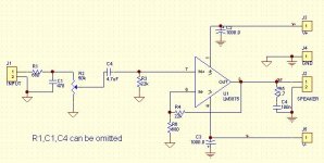
GregGC said:This is one example. I'm trying a bit different values. R6=22k, R4=470K to minimize the output DC offset to minimum.
Amazing. I was about to try this option, for exactly the same reason: lowering the offset.
Have you listen to it yet? I was going to use 220K in feedback and 6.8 to ground. I know that I should match 22K in the other input, but still, is a closer match than the circuit that is proposed to date, (22K in non inverting input and 680 ohms in inverting, right?
After all, we have been using high feedback resistors in the IGC for a long time, so the situation sould be an improvement. I've seen 1 meghom feedback used in some designs, but I feel is a little extreme.
We'll see.
Ric
Hi
@ GregGC,
Thank you very much. This is about what I was looking for. Should the pot be log or lin?
@ Ric
As far as I know* a opamp should "see" the same impedances on both inputs when used in inverted mode. When used in non-inverted mode this is not so important. Am I right? Is this true for power opamps, too?
Great forum.
Cheers
Christian.
*My knowledge is collected on the www ...
Thanks,
I got
> a dual 47K logarithmic pot here,
> two large heatsinks,
> a 2x20V transformer,
> lots of 1/2W metal film resistors,
> four 2.200uF electrolytic caps
> two 2.2uF Wima MKS for input
(i know that this smaller value will cost me some bass)
> two LM3875, of course
> two 0.1uF MKP caps
> some connectors
> some fast diode rectifiers
here. Hope this fits.
I will mount everything on the heatsink and a piece of MDF first.
Before I ruin my beloved speakers, I will measure DC on output, and try the gainclone on cheap speakers. Is there anything else I can do to make sure not to blow my equipment?
Thanks again,
Best regards
Christian.
Balancing act
Cristian,
As far as I understand it, it does not matter if it's inverting or not, the same principle aplies to any op amp, power or not.
I wonder if the difference in sound that Peter Daniel hears between NI and IGC has to be more with the resistor values than the topology.
I'd really like to know if he'd like the NIGC with 220K in feedback and 6.8K to ground.
He is the only one that can carry this experiment,but I think is asking him too much.
cheers
Ric
Re: Coincidence!
Exactly the way I was thinking. I haven't listen to it yet.
As someone already said: The pot can be linear. Actualy preferebly linear so that you get a closer match between left and right chanal, especially in stereo version. The 22k in paralel will create a sort-of-log pot out of it. If you use 100k pot instead you'll be closer to the log curve, but not such a big deal.
The parts list looks fine to me.
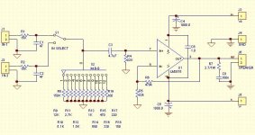
If you have SM resistors try this.
As Ric mentioned above, try playing with R4/R6, keeping the ratio the same see what combination will give you less offset at the output and see how it'll sound. Try 3.3k/68k or 6.8k/150k or 10k/220k, 15k/330k and tell us what you get. The goal is min DC on the output (single digit in mV) with the min res. values of R4/R6.
Ricren said:
Amazing. I was about to try this option, for exactly the same reason: lowering the offset.
Have you listen to it yet? I was going to use 220K in feedback and 6.8 to ground. I know that I should match 22K in the other input, but still, is a closer match than the circuit that is proposed to date, (22K in non inverting input and 680 ohms in inverting, right?
After all, we have been using high feedback resistors in the IGC for a long time, so the situation sould be an improvement. I've seen 1 meghom feedback used in some designs, but I feel is a little extreme.
We'll see.
Ric
Exactly the way I was thinking. I haven't listen to it yet.
krishu said:Hi
@ GregGC,
Should the pot be log or lin?
Christian.
As someone already said: The pot can be linear. Actualy preferebly linear so that you get a closer match between left and right chanal, especially in stereo version. The 22k in paralel will create a sort-of-log pot out of it. If you use 100k pot instead you'll be closer to the log curve, but not such a big deal.
The parts list looks fine to me.
If you have SM resistors try this.
As Ric mentioned above, try playing with R4/R6, keeping the ratio the same see what combination will give you less offset at the output and see how it'll sound. Try 3.3k/68k or 6.8k/150k or 10k/220k, 15k/330k and tell us what you get. The goal is min DC on the output (single digit in mV) with the min res. values of R4/R6.
Attachments
Interesting
Hi Greg,
I like the RF filter at the imput. I find it necesary with all the diigital interconnects and gear around here.
I rememember long discusions about the min an max gain that the amp has to be adjusted to. Aparently there are good reasons to go no less than 20 times.They were talking about 22 to 35 as sort of "golden ratio".
I wish I had the time to conduct serios listening tests with this now, but my faciliy is booked 'till the end of december. I'd realy like to sort this out.
On a second tought, may be I'm not qualified at all for a high end listening test. After all I like how my Genelec monitors sound, and for some people around here they are sort of cr-p.
cheers
Ric
Thank you so far,
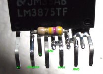
Thanks for the close-up photo.
I see you using some N/C pins (6, 9,10,11) as ground. Are you doing this just to have a place where you can solder things together and to save a pcb or MUST these pins be connected to ground? (Data Sheet does not say so.)
I originally planned just to snip off the N/C pins leaving only V-, V+, OUT and IN-, IN+.
by using a 100k pot (later on), do I have to change some resistor values?
Thanks again
Christian.
Re: Interesting
I suggest to connect the unused pins of the IC around the input area to gnd. It'll shield it even better all the way to the chip (dice). You'll have gnd on both sides of the input pins, the heat sink is gnd (in my case) too. First connect pin5 to the star gnd (th midle of the 1000uF caps) and then use the other free pins as a soldering points for the input gnd to the pot and from the pot to the RCAs. The input filter (R1,C1) should be right on the RCA (IMO). This way any unwanted RF will be killed there and not spred around inside your nicely shielded amp.
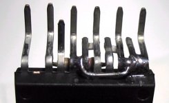
Here is the picture of the back. The pin2 I got rid of. Dont need or want to have gnd close to the ouput. Just increases the output capacintance that the amp has to drive.
Just use the 100k lin. pot, and no other resistor value changes.
Greg
I think you are quite right with the gain. I think any body qualifies for high end listening test. You may not hear some subtle details, but that means you can get away with spending less $$$ and have the same high level of enjoinment.Ricren said:Hi Greg,
I like the RF filter at the imput. I find it necesary with all the diigital interconnects and gear around here.
I rememember long discusions about the min an max gain that the amp has to be adjusted to. Aparently there are good reasons to go no less than 20 times.They were talking about 22 to 35 as sort of "golden ratio".
I wish I had the time to conduct serios listening tests with this now, but my faciliy is booked 'till the end of december. I'd realy like to sort this out.
On a second tought, may be I'm not qualified at all for a high end listening test. After all I like how my Genelec monitors sound, and for some people around here they are sort of cr-p.
cheers
Ric
krishu said:Thank you so far,
Thanks for the close-up photo.
I see you using some N/C pins (6, 9,10,11) as ground. Are you doing this just to have a place where you can solder things together and to save a pcb or MUST these pins be connected to ground? (Data Sheet does not say so.)
I originally planned just to snip off the N/C pins leaving only V-, V+, OUT and IN-, IN+.
by using a 100k pot (later on), do I have to change some resistor values?
Thanks again
Christian.
I suggest to connect the unused pins of the IC around the input area to gnd. It'll shield it even better all the way to the chip (dice). You'll have gnd on both sides of the input pins, the heat sink is gnd (in my case) too. First connect pin5 to the star gnd (th midle of the 1000uF caps) and then use the other free pins as a soldering points for the input gnd to the pot and from the pot to the RCAs. The input filter (R1,C1) should be right on the RCA (IMO). This way any unwanted RF will be killed there and not spred around inside your nicely shielded amp.
Here is the picture of the back. The pin2 I got rid of. Dont need or want to have gnd close to the ouput. Just increases the output capacintance that the amp has to drive.
Just use the 100k lin. pot, and no other resistor value changes.
Greg
Attachments
")
Hello again ...
I soldered the first channel on Tuesday evening and let it burn in overnight. On Wednesday I made One-Channel-A/B-Comparism (left Gainclone, right my NAD Integrated Amplifier C 370 appr. $800). First, i was quite surprised by the music that comes out of that tiny thing. Voices were sweet, tonality semmed to be neutral. Things sounded a bit harsh but I think this is because of the cheap components I used. (Old 2.200uF Caps, MKS in signal path). Compared to the NAD the Gainclone sounded a tad more alive, whereas the NAD was more behaved. The bass of the gainclone was very muddy compared to the controlled bottom end of the NAD. The heights with the Gainclone seemed to be cut off, whereas the NAD hat more sparkle in the treble.
To describe the circumstances a bot more in detail: the source was a NAD C541i; the LM3875 was fed by a standard transformer delivering +/-20V and quite little current. I used the circuit posted by Greg above, using 2x 22k and 1x470K and 2.7R 1/2W metal film resistors. The input cap was a WIMA MKS10 2.2uF, the RC-cap on the output was a Wima MKS 0.075uF. Wiring was rather cheap and sub-low-quality.
Unfortunately i broke one supply pin of one chip so i cannot do a long-term test at the moment, but this will follow. I will replace electrolytic caps by better ones as well as the transformers. I will try a single-TDA7293-Chipamp, too. I will post my results then. Maybe in a few weeks.
Thank you all again,
Cheers
Christian.
Christian,
Thanks for the feedback.
What was your DC offset with this setup. I was going to try and see what the min values of the FB/GND resistor are while I still have reasonable dc offset(to me, single digit, in mV).
For the base to be muddy (as you said) most likely your PS doesn't supply enough juice. At what volume levels did you make your comparison? As for the highs, I suspect the cap quality if the amp doesn't go into oscillation. How is your RF immunity. Do you have LP filter at the input or a cap across -IN and +IN?
Sorry about all the questions but it's quite interesting. I'll have mine ready soon too, so I'll report back.
Thanks again.
Greg
Reason for low offset
A member of this forum was so kind to e-mai me privately to tell me that I should relax about the offset thing, allowing 30-50 mv without problems.
But I think the issue is important in my case, because I'll be connecting some of them to the tweeter and midrange horn of a 3 way speaker. 30 mv in the tweter is not quite good, or is it?
cheers
Ric
Re: Reason for low offset
Most likely will be fine. This dc offset is my personal thing that I want to resolve for myself. Sure 30mV is fine as long as it sound right.
As I just mentioned in another tread, at gain of 20 the amp has a bandwith of 300kHz. It's one mean capable IC. It really needs a careful handling.
Greg
Ricren said:A member of this forum was so kind to e-mai me privately to tell me that I should relax about the offset thing, allowing 30-50 mv without problems.
But I think the issue is important in my case, because I'll be connecting some of them to the tweeter and midrange horn of a 3 way speaker. 30 mv in the tweter is not quite good, or is it?
cheers
Ric
Most likely will be fine. This dc offset is my personal thing that I want to resolve for myself. Sure 30mV is fine as long as it sound right.
As I just mentioned in another tread, at gain of 20 the amp has a bandwith of 300kHz. It's one mean capable IC. It really needs a careful handling.
Greg
Re: Reason for low offset
For safety, it is never a bad idea to connect a capacitor in series with the tweeter...
(but this also depends on the costs of the tweeters)
Fedde
Ricren said:A member of this forum was so kind to e-mai me privately to tell me that I should relax about the offset thing, allowing 30-50 mv without problems.
But I think the issue is important in my case, because I'll be connecting some of them to the tweeter and midrange horn of a 3 way speaker. 30 mv in the tweter is not quite good, or is it?
cheers
Ric
For safety, it is never a bad idea to connect a capacitor in series with the tweeter...
(but this also depends on the costs of the tweeters)
Fedde
- Status
- This old topic is closed. If you want to reopen this topic, contact a moderator using the "Report Post" button.
- Home
- Amplifiers
- Chip Amps
- Non-Buffered Non-Inverted Gainclone (LM3875) fpr 47K Pot Circuit Wanted