Yes you were right the results from connecting to c402 are just the same.
I have expanded on the sensitive control to help; it is set on full speaker-amp, the pre-amp balance control is full over to this speaker, this is to prevent my eardrums from bursting from the other speaker, then turn up the volume to full on the pre-amp, the sound is still the same very much lower than the pre-amp side of the control.
I agree with only your last Para about the sensitive control.
I must persist with telling you of my experience of the sensitive control, which differs from what you say, I am only doing this to help, give more understanding as the user.
When the speaker was working correctly; this is what I experienced with the sensitive control, whilst setting these speakers up from new, this is the time to find out what does what from the controls.
With music playing (not loud), turning from pre-amp to speaker-amp the sound level was unnoticeably different in volume, I remember this, and as this speaker is positioned further away from the other and difficult to gain access to alter this control, I always had this one set full on speaker-amp leaving the other speaker the one to set the balance correctly (which would be fine-tuned by turning down) when listening from my seated position (the volume setting on the pre-amp would be approx. mid-way) once this was set, you just forget about that control because it is set.
I've read what you have said several times to try and understand how you use this...
This bit puzzles me,
Are you saying that on this speaker that the sensitivity control never had much effect ? but on the other speaker it did ?
Also (and this is very very important)... when we injected the signal direct into C402 as now or particularly when it is was injected direct into 2402 and then 2401 in the previous steps... if you then turned the volume on the main preamp up toward full, was it as loud as it should be ?
In other words could you drive the speaker to full volume levels and beyond?
That is a crucial point to understanding this.
This bit puzzles me,
With music playing (not loud), turning from pre-amp to speaker-amp the sound level was unnoticeably different in volume, I remember this, and as this speaker is positioned further away from the other and difficult to gain access to alter this control, I always had this one set full on speaker-amp leaving the other speaker the one to set the balance correctly (which would be fine-tuned by turning down) when listening from my seated position (the volume setting on the pre-amp would be approx. mid-way) once this was set, you just forget about that control because it is set.
Are you saying that on this speaker that the sensitivity control never had much effect ? but on the other speaker it did ?
Also (and this is very very important)... when we injected the signal direct into C402 as now or particularly when it is was injected direct into 2402 and then 2401 in the previous steps... if you then turned the volume on the main preamp up toward full, was it as loud as it should be ?
In other words could you drive the speaker to full volume levels and beyond?
That is a crucial point to understanding this.
I've read what you have said several times to try and understand how you use this...
This bit puzzles me,
Are you saying that on this speaker that the sensitivity control never had much effect ? but on the other speaker it did ?
I am saying that; there should not be a loss of sound on either speaker when turning the sensitive control from pre-amp, over to full on speaker-amp.
Also (and this is very very important)... when we injected the signal direct into C402 as now or particularly when it is was injected direct into 2402 and then 2401 in the previous steps... if you then turned the volume on the main preamp up toward full, was it as loud as it should be ?
In other words could you drive the speaker to full volume levels and beyond?
That is a crucial point to understanding this.
With the sensitive control on speaker-amp no.
.................................................................
I had hoped my previous post was simple to understand; it is very difficult trying to get the message across.
I need to understand that part of the drawing on the audio input going through to the main amplifier, how it works, but not today, I need a rest from this, it is very frustrating for me, maybe you too?
The problem with this speaker is there is no amplification produced when the sensitive control is turned to full on speaker-amp; if we can sort this out then it will be working.
With the sensitive control on pre-amp the speaker works fine in that mode.
I'll explain how it works later... I'll try and make it easy to understand ")
Off the wall thought because you say the speaker works fine in 'pre amp' mode. That all sounds fine to me (and I know from looking at the circuit it is fine).
Don't shout Could the other speaker be the faulty one ? and not behaving correctly ??? Could that speaker be the one that is to loud in comparison to this one ??
Something easy to try without dismantling or altering anything.. and I don't think we've done this...
With both speakers OFF just try measuring the resistance between C401 (ground) and C402 and compare the result between speakers. You can do that from the preamp leads if you want because they go to the same point. Just compare the two readings with the pot at each setting. They should be the same of course between speakers.
When its all explained you'll see how it works and why I think this one is behaving correctly.
Off the wall thought
because you say the speaker works fine in 'pre amp' mode. That all sounds fine to me (and I know from looking at the circuit it is fine). Don't shout
Could the other speaker be the faulty one ? and not behaving correctly ??? Could that speaker be the one that is to loud in comparison to this one ??Something easy to try without dismantling or altering anything.. and I don't think we've done this...
With both speakers OFF just try measuring the resistance between C401 (ground) and C402 and compare the result between speakers. You can do that from the preamp leads if you want because they go to the same point. Just compare the two readings with the pot at each setting. They should be the same of course between speakers.
When its all explained you'll see how it works and why I think this one is behaving correctly.
Thank you for your willingness to explain to me about understand that part of the drawing on the audio input going through to the main amplifier, how it works, it could be better for me to ask the questions to gain this understanding, I need to think how’s the best way to achieve this.
The problem with this speaker is there is very little amplification when the sensitive control is on speaker-amp setting; we need to find this fault.
Please note; that the sensitive control has been left set on full speaker-amp setting and it has worked well for 30 years, and then it lost almost all amplification, meaning you had to put your ear to the speaker to hear sound.
To explain this you first of all need to understand the basics of ohms law and how variable controls such as the pot work.
The pot (any pot, or any small preset trimmer pot is the same) is simply a resistive track of carbon with two fixed contacts at each end together with a third moving contact that can run the length of the track.
Example... imagine a pencil lead in front of you. Pencil leads are poor conductors having the property of resistance. Lets say you measured the resistance of it from end to end on your meter and found it read 1000 ohms. So far so good. We can now use ohms law to calculate all kinds of things knowing just that.
If you connected a 10 volt battery across the pencil lead then a current of I=V/R or 10/1000 would flow. Thats a current of 0.01 amps or 10 milliamps if you prefer.
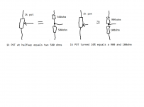
If you now moved one of the meter leads from the end of the pencil lead and slid it up and down the pencil lead then you would see the voltage change. This is what the middle wiper leg of the pot does. It is just a moving contact along the resistive track. If you placed it half way along then you would measure 5 volts, move it 80 % of the way along and you read 8 volts and so on. In the half way position it is the equivalent of two 500 ohms in series with the wiper being the junction of the two resistors. Each resistor drops 5 volts, and the total drop of the two together is 10 volts, our applied voltage. If you moved the pot 10 % of the way around then the wiper is 10% of the way along the track. So the equivalent for that would be two resistors, one of 900 ohms and one of 100 ohms. See diagram attached.
So in summary... it is how far round the pot is turned that determines what percentage of the applied voltage appears on the wiper. Its infinitely variable from zero to 100% of the applied voltage.
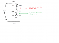
So lets try and explain the input stage of the speaker. The equivalent circuit is shown below and consists of 3404, 3400 and 3405 effectively appearing in series. The cap 2401 appears as a short circuit to the wanted signal. The tiny 180 pf cap is to small to affect the audio frequencies... its just to filter radio interference and the like. So both caps can be ignored. We could calculate their equivalent resistances an inculde them in the calculation but there is no point, one appears as a short circuit and one appears as open circuit.
The three resistors in series add up to 114700 ohms. I know yours measure a bit different, that doesn't matter as you will see.
We can look for real at what happens using two examples, one with the pot on preamp and one on speaker. The other section of the pot 3401 I will explain in a moment... it doesn't alter anything that happens here.
Pot on 'preamp'setting. This has the wiper turned up full so that it contacts 3404 (the cap appears as a short for audio remember). So I can put imaginary but realistic numbers in for signal level. We'll say the preamp is putting out 1 volt. The current is I=V/R which is 1/114700 which is 8.7 micro amps. Now we can work out the voltage at each point in that chain. Volts is equal to current times resistance and so the 10k sees 87 millivolts across it. The 100k pot sees 870 millivolts and the 4k7 sees 41 millivolts. Add those up as a check and we get back to our applied 1 volt.
So I know by looking at the circuit that with the pot on full you will get 957 millivolts (the 87 + 870 across the 10k and pot) for every volt applied.
With the pot on minimum (speaker setting) it will see just the 87 millivolts that is across the 10k.
These are the signal levels that are applied to the circuit and so with the pot on 'speaker' it cuts the applied level down from nearly the full 1 volt right down to just 87 millivolts.
The whole point of the control is to allow you to apply a signal that has already been amplified, a signal that could be in the 10 to 30 volt range.
Applying 10 volts with the pot on 'speaker' would work a follows. Current is 10/114700 which is 0.087 milliamps. Voltage across the 10k lower resistor would be 870 millivolts. Thats in the correct sort of range for the circuitry. First example had 1 volt from the preamp, second example had 10 volts from an external power amplifier applied.
So its correct that the pot should only work with the preamp when its in the preamp position Honest. When its in the speaker position it will attenuate the signal drastically.
Ok, so what about the other section of the pot. Well that doesn't alter anything explained above. All the second section of the pot can do is add a load to the preamplifier which can alter the applied voltage yes, but it doesn't alter the way the main section of the control works.
So how does it alter the applied voltage...
Well it can only do so by interaction with the unknown value of the output resistance of the preamp. So I can see you thinking 'well is there something going on there then ?' ad the answer has to be no, simply because you have proved by swapping feeds around that the preamp ouput on that channel is good.
Lol, so where does this leave things... well I'm honestly thinking (bareing ? bearing ?? bearing in mind you say this speaker is good on the preamp setting) is that either this speaker has had an issue that for some reason no longer exists (because its working as it should when you turn that level control) or that the other speaker is the faulty one... because that should alter its level as the pot is turned just as this one does. Or both possibilities. Pots are notoriously unreliable with regard to the moving contact. It could have become intermitent on one or both speakers and on one or both gangs in each. Have you given both a squirt (WD40... everyone shouts when I mention WD40) but it works. Don't flood them, just a quick blast into the open part of the pot where you can see the innards and then turn each to and fro a dozen times quickly.
The pot (any pot, or any small preset trimmer pot is the same) is simply a resistive track of carbon with two fixed contacts at each end together with a third moving contact that can run the length of the track.
Example... imagine a pencil lead in front of you. Pencil leads are poor conductors having the property of resistance. Lets say you measured the resistance of it from end to end on your meter and found it read 1000 ohms. So far so good. We can now use ohms law to calculate all kinds of things knowing just that.
If you connected a 10 volt battery across the pencil lead then a current of I=V/R or 10/1000 would flow. Thats a current of 0.01 amps or 10 milliamps if you prefer.
If you now moved one of the meter leads from the end of the pencil lead and slid it up and down the pencil lead then you would see the voltage change. This is what the middle wiper leg of the pot does. It is just a moving contact along the resistive track. If you placed it half way along then you would measure 5 volts, move it 80 % of the way along and you read 8 volts and so on. In the half way position it is the equivalent of two 500 ohms in series with the wiper being the junction of the two resistors. Each resistor drops 5 volts, and the total drop of the two together is 10 volts, our applied voltage. If you moved the pot 10 % of the way around then the wiper is 10% of the way along the track. So the equivalent for that would be two resistors, one of 900 ohms and one of 100 ohms. See diagram attached.
So in summary... it is how far round the pot is turned that determines what percentage of the applied voltage appears on the wiper. Its infinitely variable from zero to 100% of the applied voltage.
So lets try and explain the input stage of the speaker. The equivalent circuit is shown below and consists of 3404, 3400 and 3405 effectively appearing in series. The cap 2401 appears as a short circuit to the wanted signal. The tiny 180 pf cap is to small to affect the audio frequencies... its just to filter radio interference and the like. So both caps can be ignored. We could calculate their equivalent resistances an inculde them in the calculation but there is no point, one appears as a short circuit and one appears as open circuit.
The three resistors in series add up to 114700 ohms. I know yours measure a bit different, that doesn't matter as you will see.
We can look for real at what happens using two examples, one with the pot on preamp and one on speaker. The other section of the pot 3401 I will explain in a moment... it doesn't alter anything that happens here.
Pot on 'preamp'setting. This has the wiper turned up full so that it contacts 3404 (the cap appears as a short for audio remember). So I can put imaginary but realistic numbers in for signal level. We'll say the preamp is putting out 1 volt. The current is I=V/R which is 1/114700 which is 8.7 micro amps. Now we can work out the voltage at each point in that chain. Volts is equal to current times resistance and so the 10k sees 87 millivolts across it. The 100k pot sees 870 millivolts and the 4k7 sees 41 millivolts. Add those up as a check and we get back to our applied 1 volt.
So I know by looking at the circuit that with the pot on full you will get 957 millivolts (the 87 + 870 across the 10k and pot) for every volt applied.
With the pot on minimum (speaker setting) it will see just the 87 millivolts that is across the 10k.
These are the signal levels that are applied to the circuit and so with the pot on 'speaker' it cuts the applied level down from nearly the full 1 volt right down to just 87 millivolts.
The whole point of the control is to allow you to apply a signal that has already been amplified, a signal that could be in the 10 to 30 volt range.
Applying 10 volts with the pot on 'speaker' would work a follows. Current is 10/114700 which is 0.087 milliamps. Voltage across the 10k lower resistor would be 870 millivolts. Thats in the correct sort of range for the circuitry. First example had 1 volt from the preamp, second example had 10 volts from an external power amplifier applied.
So its correct that the pot should only work with the preamp when its in the preamp position
Honest. When its in the speaker position it will attenuate the signal drastically.Ok, so what about the other section of the pot. Well that doesn't alter anything explained above. All the second section of the pot can do is add a load to the preamplifier which can alter the applied voltage yes, but it doesn't alter the way the main section of the control works.
So how does it alter the applied voltage...
Well it can only do so by interaction with the unknown value of the output resistance of the preamp. So I can see you thinking 'well is there something going on there then ?' ad the answer has to be no, simply because you have proved by swapping feeds around that the preamp ouput on that channel is good.
Lol, so where does this leave things... well I'm honestly thinking (bareing ? bearing ?? bearing
in mind you say this speaker is good on the preamp setting) is that either this speaker has had an issue that for some reason no longer exists (because its working as it should when you turn that level control) or that the other speaker is the faulty one... because that should alter its level as the pot is turned just as this one does. Or both possibilities. Pots are notoriously unreliable with regard to the moving contact. It could have become intermitent on one or both speakers and on one or both gangs in each. Have you given both a squirt (WD40... everyone shouts when I mention WD40) but it works. Don't flood them, just a quick blast into the open part of the pot where you can see the innards and then turn each to and fro a dozen times quickly.Attachments
I understand Mooly all that you have said; and as a layman in this area I cannot disagree.
The 3400, 3401 Tandem Potentiometer (100kΩ resistor lineair) control might have been slightly adjusted on the odd occasion, you could say it has been static over the years; it was always in the speaker-amp side of the control (see page1 post 4, information 5. PDF it shows the numbers related to this control; it would have been set on power amp side, number 11), so I now ask, can it wear out in this static position?
I do have WD40 as well as Servisol Super 10 this is highly recommended for this kind of job, what you think!
If you look on page 2 post 13 you can see the room available to service this, and in my Service PDF page 10 item 80 it looks like you can disassemble this control centre?
If you remember I said I would like to your help to explain to me about understand of that part of the drawing on the audio input going through to the main amplifier, how it works.
This is how I would like to proceed; in the attached PDF we will work of the 2 drawings called Board B and Line Drawing (of B). I will add more information to these as it becomes understandable. The first process is to apply red arrows only in the direction that the audio single goes, and the sensitive control is over to the speaker/power-amp; will this make a difference in any of the directions?
Attachments
Servisol is OK as long as you are careful not to get it onto any plastics. Used to use this stuff years ago (maybe its changed) and it was notorious for slowly softening and attacking plastics. I've seen dozens of TV's get scrapped because of this... engineers squirting button units and controls and then weeks and months later the cabinets literally rotted and crumbled away in the area that had seen the stuff applied.
So use it carefully, use the straw, and aim it directly into the pot which in that picture is the bit that's out of sight (where the leads emerge from it).
Pots can only wear out by the resistive track becoming worn but they can also fail due to the moving contact becoming weak and intermittent or by a build up of dirt on the track. Yours wont be worn, just give them a few turns each way to clean the moving contact up.
I mentioned a few posts back about comparing the DC resistance each speaker presents across its input and also to compare one with the other... it really is worth doing !
In fact I've thought more on this aspect because its just so weird a feature (that first gang of the pot and what it does) and I've revised my thinking in that it might simply place resistor 3403 in circuit when in 'speaker/amp mode' purely to account for the fact that some amplifiers may well be AC coupled at their outputs and so need a resistive path like this to quickly charge that coupling capacitor. It would make more sense for it to operate like this than how I previously suggested.
What does that mean for you ?... well it doesn't really change anything when in preamp mode. It still all behaves as I have outlined in all the above posts.
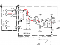
Signal flow is a progression from left to right but there is more to it than that.
So to answer your question... the red line shows the signal flow when the pot is in the speaker position.
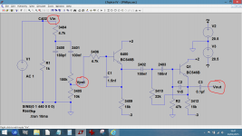
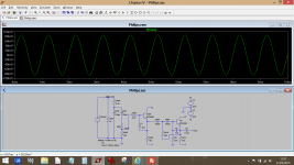
The next image shows the circuit in a simulator.
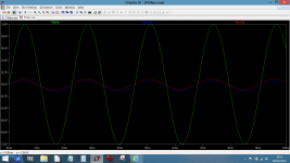
We then have a graph showing the signal levels. The pot is at the speaker/amp position and there are three voltages being measured. First is Vin which is set to 1 volt peak of signal. This is the voltage your preamp puts out. Second is 'Vpot' which is the signal voltage as measured on the pot wiper and finally is Vout which is the final signal output from this stage.
So that shows the signal path and levels in speaker/amp position of the pot.
So use it carefully, use the straw, and aim it directly into the pot which in that picture is the bit that's out of sight (where the leads emerge from it).
Pots can only wear out by the resistive track becoming worn but they can also fail due to the moving contact becoming weak and intermittent or by a build up of dirt on the track. Yours wont be worn, just give them a few turns each way to clean the moving contact up.
I mentioned a few posts back about comparing the DC resistance each speaker presents across its input and also to compare one with the other... it really is worth doing !
In fact I've thought more on this aspect because its just so weird a feature (that first gang of the pot and what it does) and I've revised my thinking in that it might simply place resistor 3403 in circuit when in 'speaker/amp mode' purely to account for the fact that some amplifiers may well be AC coupled at their outputs and so need a resistive path like this to quickly charge that coupling capacitor. It would make more sense for it to operate like this than how I previously suggested.
What does that mean for you ?... well it doesn't really change anything when in preamp mode. It still all behaves as I have outlined in all the above posts.
Signal flow is a progression from left to right but there is more to it than that.
So to answer your question... the red line shows the signal flow when the pot is in the speaker position.
The next image shows the circuit in a simulator.
We then have a graph showing the signal levels. The pot is at the speaker/amp position and there are three voltages being measured. First is Vin which is set to 1 volt peak of signal. This is the voltage your preamp puts out. Second is 'Vpot' which is the signal voltage as measured on the pot wiper and finally is Vout which is the final signal output from this stage.
So that shows the signal path and levels in speaker/amp position of the pot.
Attachments
Because you ask.
The service manual, the user manual and the schematic all indicate that the sensitive control should be set to PRE-AMP when connected to a pre-amp. Now if speaker also has the highest volume at that setting the answer seems obvious to me.
To confirm that there is actually a problem, set the sensitive controls on both speakers to maximum PRE-AMP setting, apply an input signal and compare the voltages of the bass drivers.
We'll have to wait for Michael to elaborate on this but I suspect the (this) speaker is working correctly.
This was one of the things that make me suspect the problem could be related to the other unit. This reads as if the control on the other unit has little effect which would rather suggest a problem with that speakers attenuator rather than this one.
This was one of the things that make me suspect the problem could be related to the other unit. This reads as if the control on the other unit has little effect which would rather suggest a problem with that speakers attenuator rather than this one.
With music playing (not loud), turning from pre-amp to speaker-amp the sound level was unnoticeably different in volume, I remember this, and as this speaker is positioned further away from the other and difficult to gain access to alter this control, I always had this one set full on speaker-amp leaving the other speaker the one to set the balance correctly (which would be fine-tuned by turning down) when listening from my seated position (the volume setting on the pre-amp would be approx. mid-way) once this was set, you just forget about that control because it is set.
Thank you Mooly, the red line was helpful in your first image; I have updated both drawings with questions to find more understanding.
We measured the vac on both input’s (not dc resistance as you mentioned) going into each speaker; see page 24, post 231.
Having read Mark’s posts I suspect he’s a non-user (does not have a set of these speakers) I say this because; he cannot relate to my situation.
When I quoted this “With music playing (not loud), turning from pre-amp to speaker-amp the sound level was unnoticeably different in volume,” what do you think this means? it means no difference, you will need to read the full post, see posts 259, 260, 261.
Attachments
To answer your questions.
The audio signal arrives 3400\1 and 3401\5 at the same time this is correct, yes?
Yes it does.
3401 there is a 100k resistor built-in to this pot; on the line drawing shows the lower half from connections 5 to 6 filled in what does this indicate; that the wiper has no contact in this area?
This is the bit we are not sure of. Its not drawn as a standard component. If you do the DC resistance check I keep mentioning and also by comparison to the other unit we would get a better idea. I'm guessing that with the pot on 'preamp' it reads either open circuit or 100k and with the pot on 'speaker' that it reads 1k. That's the resistance measured across the input sockets.
I know that is the opposite of what I stated at the beginning... it just makes more sense that its sole function is to provide a DC path for an AC coupled power amplifier that might get connected to it rather than a variable load on the preamp output. You'll have to take on trust that either version wouldn't alter what happens when its connected to just the preamp.
And that being related to the Sensitive Control moving off 4 to 5 or 5 to 6 has an effect on the audio signal?
6 is connected to ground, and 4 is just a connection going nowhere, it’s only purpose that I can see is providing a test point, to test this 100k you would then think to test this resistor, connect to 4 and 6?
No, this half of the control (3401) doesn't affect the gain at all. I can demonstrate that very easily in the simulation.
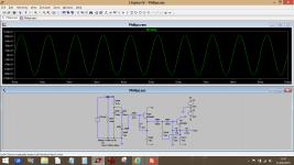
This shows 3401 set as 100k and as 1k. 3400 remains in 'Speaker' position. I know you can't turn them independently but this will show that 3401 has no effect on the gain.
We are applying 1 volt to the input. The output of the complete stage is just over 80 millivolts because 3400 is set to attenuate fully.
The simulation confirms the long hand method I used to calculate it all earlier was correct.
We are applying 1 volt to the input. The output of the complete stage is just over 80 millivolts because 3400 is set to attenuate fully.
The simulation confirms the long hand method I used to calculate it all earlier was correct.
With the pot on minimum (speaker setting) it will see just the 87 millivolts that is across the 10k.
These are the signal levels that are applied to the circuit and so with the pot on 'speaker' it cuts the applied level down from nearly the full 1 volt right down to just 87 millivolts.
Attachments
I am a non owner, but I have installed these speakers for other people. Philips sold many of these speakers in Holland.
But that is not the point, if you just read the user manual, the service manual or the sim that Mooly has done, you can only come to one conclusion, the speaker is set to PRE-AMP when connected to a pre-amp and POWER-AMP when connected to a power amp.
Input <3 Volt is Pre-amp.
Input 3-25 Volt is Power amp.
You have measured the input at about 1 volt RMS.
Quote:
This is the bit we are not sure of. Its not drawn as a standard component. If you do the DC resistance check I keep mentioning and also by comparison to the other unit we would get a better idea. I'm guessing that with the pot on 'preamp' it reads either open circuit or 100k and with the pot on 'speaker' that it reads 1k. That's the resistance measured across the input sockets.
3401 resistance test results; (test a) on 4 and 6 gives 0.L (no reading).
Sensitive Control on pre-amp, (test b) on 4 and 5 gives 00.2Ω, and (test c) on 5 and 6 gives 0.L.
Sensitive Control on speaker-amp, (test d) on 4 and 5 gives 0.L (test e) on 5 and 6 gives 00.2Ω.
We cannot move on from this point; there should be a reading of 100k showing. Note when this fault occurred it was sudden not gradual.
Another interesting point that I have just seen now I have the red arrows to follow is; and I can see both drawings at once; this audio (1 of 2) coming from c402 arrives at 5 and finds its way internally to 2; it is the broken line (I referred to this in post 98 page 10) we haven’t done any resistance checks on 2 and 5?
Before I mentioned; on the line drawing shows the lower half from connections 5 to 6 filled in; I am still thinking that the wiper has or has no contact in this area.
I’m just thinking aloud here ok; with the Sensitive Control over to one side, the audio signal goes through 5 and then 2. With the Sensitive Control over to the other side the audio signal goes through 1 and then 2. This would dropout some of the components from being activated?
I think you may well have something with what you said earlier quote:
“In fact I've thought more on this aspect because its just so weird a feature (that first gang of the pot and what it does) and I've revised my thinking in that it might simply place resistor 3403 in circuit when in 'speaker/amp mode' purely to account for the fact that some amplifiers may well be AC coupled at their outputs and so need a resistive path like this to quickly charge that coupling capacitor. It would make more sense for it to operate like this than how I previously suggested.”
The other speaker, hmmm, well you did ask, please read post 4.
I am posting this now, even though there is much more to comment on; thank you Mooly and Mark.
The other speaker had a whole new amp board fitted, is that the bit you mean ?
We cannot move on from this point; there should be a reading of 100k showing. Note when this fault occurred it was sudden not gradual.
You can compare the result with the other speaker just by measuring across the leads to the preamp. Switch both speakers off first though. This is what I keep wanting you to do.
Just measure the resistance at both extremes of the pot setting for both speakers.
You see, no matter what that section of the pot does, it can only add 1k or higher loading to the preamp (resistor 3403) and so that gang of the control has no effect on the preamp output.
- Status
- This old topic is closed. If you want to reopen this topic, contact a moderator using the "Report Post" button.
- Home
- Amplifiers
- Chip Amps
- Philips 22AH587 replica modules