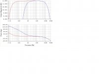
Taking Scheme A with its magnitude and phase versus frequency as shown in Figure B (blue curve), I make an invitation to the community to achieve similar frequency response (magnitude and phase), as shown in Figure B (red curve). To accomplish this, one has to use the same components shown in Scheme A (referring to quantity, type and value). Not allowed to remove or add components as those shown in Scheme A (you must use the same components, to achieve the objective of this challenge). The input signal must remain AC coupled. The high frequency response must remain similar (over 10 KHz). The voltage gain in the passband should remain similar (3.92). The input impedance in the passband should remain similar as well. The output is applied over the 10K resistor. This 10K resistor must continue to fulfill the function as output load in the new proposal. Another thing is that is not allowed in the attempt to generate offset problems at the same stage.
The answer to this challenge's available to me, since I am the mentor of this exciting discovery.
With this new interconnection between components, we can achieve these and many other improvements.
Everything is in the process of being patented. That is why the new scheme can not be shown yet. It can be applied to the field of audio, among other applications.
As soon as I get the title of the invention, I'm going to explain in detail.
regards
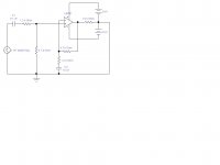
Scheme A:

Figure B:

The answer to this challenge's available to me, since I am the mentor of this exciting discovery.
With this new interconnection between components, we can achieve these and many other improvements.
Everything is in the process of being patented. That is why the new scheme can not be shown yet. It can be applied to the field of audio, among other applications.
As soon as I get the title of the invention, I'm going to explain in detail.
regards
Scheme A:
Figure B:
Attachments
Last edited:
Not sure I fully understand.
Are you asking for a different way to connect the same parts for the same results? If yes, what's the advantage of it, apart from the intellectual challenge? If the same parts give the same results, whats the improvements you mention?
I assume that there is some advantage that is the subject of the patent?
Why do you attenuate the input signal?
Did you apply already for the patent? This can take several years easily.
jan
Are you asking for a different way to connect the same parts for the same results?jan
No. Different way to connect the same parts for better results.
I assume that there is some advantage that is the subject of the patent?jan
Yes. Improvement ratio between lower cutoff frequencies is proportional to the ratio of C2 to C1 and inversely proportional to the gain of the system (+1 in this case). It's what I can say for now.
I dimmed the entrance to the circuit simply because it is an example for the challenge, although it could have been a simple non-inverting configuration.
The patent is in process. Yes, it will take some time to emerge definitively.
I have concrete evidence that this is working very well. Even now I have it implemented in a pure class A amplifier.
This new connection may give characteristics next to the directly coupled systems, but with the advantages of AC coupled systems.
Regards
Last edited:
No. Different way to connect the same parts for better results.
[snip]Regards
Better in what way? You ask for the same (similar) passband and phase curve. If you want the same performance with the same parts it is not much of a challenge. If it really is a challenge, in what way must it be better?
jan
Better in what way? You ask for the same (similar) passband and phase curve. If you want the same performance with the same parts it is not much of a challenge. If it really is a challenge, in what way must it be better?
jan
Let's see ... What you have to get are the red curves (the main objective, in the example given).
I give an example: if, in your attempt, you exchange C1 to C2, and vice versa, leaving all other components in the original position, obviously you can not get the red curve given. The lower cutoff frequency (-3 dB) of this change is around 1.26 KHz (far from around 6.67 Hz, corresponding to the red curve).
In a similar way to the example given I suggest trying to get to the red curves.
Am I clear?
PD: One advantage is a significant increase in bandwidth (to the side of low frequencies, using for this small capacitors). There are many other advantages.
Regards
Hi,
This is an exercise in tedium. There is nothing you can have "discovered"
about such a simple circuit that hasn't been done before and I expect
whatever you think you've "discovered" is fundamentally flawed.
I'm not excited. I'm bored. You can't do what you say. There is
no right answer because what you think it is, is simply wrong.
The challenge is to guess what you've got wrong.
My guess in no DC path for an input.
rgds, sreten.
Last edited:
Hi,
This is an exercise in tedium. There is nothing you can have "discovered"
about such a simple circuit that hasn't been done before and I expect
whatever you think you've "discovered" is fundamentally flawed.
I'm not excited. I'm bored. You can't do what you say. There is
no right answer because what you think it is, is simply wrong.
The challenge is to guess what you've got wrong.
rgds, sreten.
This is not an exercise. In fact is laboratory tested. I have also implemented a pure class A amplifier, as I said.
And the proposal is not tricky!. Believe me that's how I say it.
This does not go against the laws of physics.
The improvement ratio of the lower cutoff frequency for this example is about 40.68 times.
Just as the circuit is so simple, I invite you to get similar results, without doubt your abilities.
regards
GoatGuy:
Is everything okay with the analysis you've done, but this analysis corresponds to the example presented (which is deductible, for its simplicity)
Again, the question is what is the configuration that achieves the red curves?. Obviously, using all the components given (in another connection).
regards
Does the "new" version have to be stable if the input is left open circuit ?
Yes.
Hi,
This is dull. Some form of bootstrapping might work
but its hardly like that hasn't been done before.
rgds, sreten.
Do not be discouraged. There is a way and allows us to apply it to all currently known (with a very few changes). Like everything else, employment restrictions may apply in some areas.
regards
Are you going to say you have re-connected the "first" 4K7 across the inputs to the opamp. That is between pins 2 and 3 ?
No. But I can not give much more help (please understand me)
Anyway, check if what you propose meets the requirements given.
regards
Ok, go patent it and revolutionize electronics.
Good luck.
PS: as you see, I don't think there's much meat in your discovery, but letting that aside, what you are doing is foolish, because if somebody guesses what you are trying to do , and posts that answer here, which is a public and widely known Forum, that alone basically turns it into a public domain idea.
Or worse: even if it were something patentable (of which I'm not so sure, and that's an understatement), anybody who "guesses" it, *without* your help, (which is easy to prove just reading your posts), will automatically be a BIG challenge to your rights (if any).
Funny thing is that you are posting in a Forum full of intelligent people, and wrapping it in a challenge.")
Talk about walking in a minefield !!!
Good luck.
PS: as you see, I don't think there's much meat in your discovery, but letting that aside, what you are doing is foolish, because if somebody guesses what you are trying to do , and posts that answer here, which is a public and widely known Forum, that alone basically turns it into a public domain idea.
Or worse: even if it were something patentable (of which I'm not so sure, and that's an understatement), anybody who "guesses" it, *without* your help, (which is easy to prove just reading your posts), will automatically be a BIG challenge to your rights (if any).
Funny thing is that you are posting in a Forum full of intelligent people, and wrapping it in a challenge.
Talk about walking in a minefield !!!
OK, here it is.
By the way, as mentioned by *many*, that's called "bootstrap" and is as old as the mountains.
Meets all constraints, of course.
Including stability, reliable DC path to ground, etc.
And no, it does *not* behave "as a DC coupled circuit" as you seem to believe.
Mainly because no capacitor coupled input amplifier passes DC.
An externally hosted image should be here but it was not working when we last tested it.
By the way, as mentioned by *many*, that's called "bootstrap" and is as old as the mountains.
Meets all constraints, of course.
Including stability, reliable DC path to ground, etc.
And no, it does *not* behave "as a DC coupled circuit" as you seem to believe.
Mainly because no capacitor coupled input amplifier passes DC.
Hi,
Seems you can patent just about any old nonsense nowadays,
if you pay for it, and given the patent is legally challengeable,
any real "due process" only starts when you try to enforce it.
Great for patent lawyers, very poor for the gullible.
Long gone are the days when Einsteins worked in patent offices,
basically clueless penpushers nowadays, with no responsibility
at all regarding patent rights and infringements, that is legal.
rgds, sreten.
- Status
- Not open for further replies.
- Home
- Amplifiers
- Chip Amps
- Opamp challenge