I have a question
The circuit in post 1 could be duplicated (i.e. two built) and then be fed from a "normal" source such as a CD player etc. Both circuits would in that case operate independently of course.
Can your "new" circuit like-wise be duplicated in the same way and two the "channels" operate independently when fed from a "common" source.
Just a wonderin
Yes. In my amp I have it working in the same way.
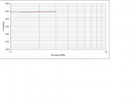
I am almost certain I knew exactly what the Op did, as I've done it in the past. I had put pictures of it up on imageshack and shared with a few friends this past autumn, and it offered a flat phase and response from less than 1Hz to over 100kHz. I'm running some models to try and remember.
Last edited:
Hi,
Really ? How do you know that ? You'd have to know the supposed
solution and your stuff to be any judge of the merits of this thread.
I know it because I'm smart. Like a lot of folks here are. And no one has come up with a correct solution yet. Which does support the claim of novelty.
I've already posted how you usually would do it, and it works.
No, not true.
If you could actually post a solution to the puzzle then you would be the winner of the challenge, instead of just another loser.
Sure, there may not be any solution, but I think the OP actually does have one. But those who don't like the challenge don't seem to be making that argument anyway. They seem to be arguing that the challenge is just too simple and mundane to bother with, that the solution is beneath them. That's what makes it so damn amusing.
I had put pictures of it up on imageshack, so I'm running some models to try and remember. The values I used were obviously different at that time and thus so was the response & phase, but still better than +/- 0.1dB from 1-100kHz, less than +/- 2 degrees.
An externally hosted image should be here but it was not working when we last tested it.
I know it because I'm smart. Like a lot of folks here are. And no one
has come up with a correct solution yet. Which does support the claim
of novelty.
No, not true.
If you could actually post a solution to the puzzle then you would be the winner of the challenge, instead of just another loser.
Sure, there may not be any solution, but I think the OP actually does have one. But those who don't like the challenge don't seem to be making that argument anyway. They seem to be arguing that the challenge is just too simple and mundane to bother with, that the solution is beneath them. That's what makes it so damn amusing.
Hi,
Well that is all we need, more self opiniated egotistical pretension.
You know because your smart ?
What an utterly limp argument that suggests the exact opposite.
If your so smart and clever rather than a loser, post the "solution",
rather than whining about attitudes you are presuming to be the case.
Or say something that indicates you understand anything about it.
rgds, sreten.
Last edited:
diego,
If it is what I think it is (my turn to be "misterious") you'll need to plot inputZ vs. Freq.
Something nasty will turn up...Your signal source will have to drive a dead short past ~10kHz or so...therfore distorsions will raise signifcantly wrt Freq. The classA amps can't save the day here.
If it is what I think it is (my turn to be "misterious"
) you'll need to plot inputZ vs. Freq. Something nasty will turn up...Your signal source will have to drive a dead short past ~10kHz or so...therfore distorsions will raise signifcantly wrt Freq. The classA amps can't save the day here.
Last edited:
magdrop:
Thanks for joining!.
In my humble opinion I think that there are no losers, while we can salvage something positive from these or other threads.
My greatest respect.
kouiky:
WOW!. I am expectant that may exist more than one solution.
This can be very interesting.
regards
sidiy:
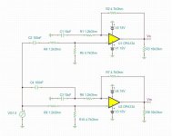
You can upload the schematic?
I'll try to post what you ask, or at least tell you if something like that happens. Give me a little time, please.
regards
Thanks for joining!.
In my humble opinion I think that there are no losers, while we can salvage something positive from these or other threads.
My greatest respect.
kouiky:
WOW!. I am expectant that may exist more than one solution.
This can be very interesting.
regards
sidiy:
You can upload the schematic?
I'll try to post what you ask, or at least tell you if something like that happens. Give me a little time, please.
regards
Last edited:
sidiy:
You can upload the schematic?
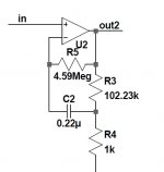
Of course! With only one modification it satisfies all the conditions and gives the same simulated results. The bad news is that it loads the source pretty badly so in applications for audio one must consider headphone type outputs with care for stability, distorsions...etc.
Attachments
Yes. In my amp I have it working in the same way.
Thanks... my reason for asking was this... to confirm that two identical circuits can have either the "negative" or the "positive" of their respective signal sources joined together (as would happen with a CD player with the negatives being common) and that both circuits would still operate correctly
I haven't been able to figure out how to meet all the requirements. The circuit I offered earlier that matched your phase and amplitude plots almost exactly, removed the ground referencing of the input source.
The input impedance is one area where my solution failed too.
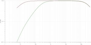
If the input impedance in the pass band remains the same as the original then that suggests we should be able to add a 5.9K in series with the source voltage and that the output voltage will reduce by 50% without affecting the response.
If the input impedance in the pass band remains the same as the original then that suggests we should be able to add a 5.9K in series with the source voltage and that the output voltage will reduce by 50% without affecting the response.
By the way did any of you read Castor-Perry's article in Linear Audio?
jan
I must confess I haven't...
sidiy:
I mounted breadboard the two options ("standard" and "modified") and measured input impedance in both circuits above 10 KHz. There may be slight discrepancies in the readings but I do not see major differences.
regards
jan.didden:
I'll look for that article. Looks interesting.
Clarified that is not what I'm using.
Thank you very much for the information.
regards
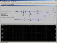
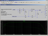
Attachments
astx:
Those were the two best approximations, until now. Give me some time to analyze them in detail.
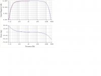
I do not see these nonlinearities, as I said occurs in other case.
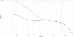
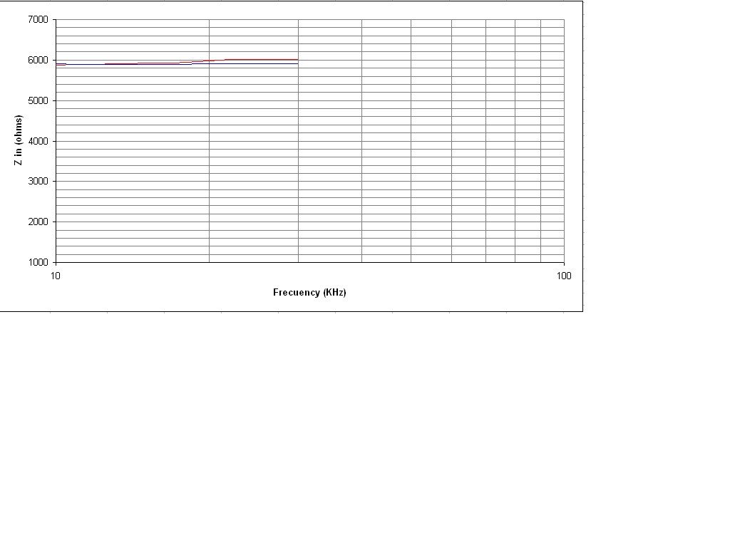
I have doubts on the input impedance. I think it's 2K4.
As you can see, I use another variant.
The blue curve corresponds to what You have kindly uploaded.
regards

Those were the two best approximations, until now. Give me some time to analyze them in detail.
I do not see these nonlinearities, as I said occurs in other case.
I have doubts on the input impedance. I think it's 2K4.
As you can see, I use another variant.
The blue curve corresponds to what You have kindly uploaded.
regards
Attachments
Last edited:
Mooly:
Yes. These were measured on a real case.
regards
astx:
The blue curve is more linear than red (no doubt). However, in real cases, this nonlinearity does not exceed 0.1 dB. Believe me it is so.
The main intention in my connection is:
Given a common connection, have the possibility to relocate its components, maintaining its current parameters and improve only the low-frequency response (without prejudice to the other parameters). This would allow us to implement it in all that exists, relocating connections only.
While what you have is very interesting, would have to find a way to keep the same input impedance (or something very similar).
regards
- Status
- Not open for further replies.
- Home
- Amplifiers
- Chip Amps
- Opamp challenge