(we are all intrigued)
Hi,
No we are not. Some of us are utterly bored. Why explore options for
someone based on some totally pretentious claims, that allow the
goalposts to be moved at anytime depending on the information
received, and excuses as to never define where they actually are.
rgds, sreten.
Looking at this from an entirely different perspective.......
That is a very good approximation. You'll notice that this is not the one I use, yet.
I've been testing and studying this setup for almost a year. If you try different combinations of capacitors, will verify certain nonlinearities at low frequencies (depending on the ratio of capacitors). Try, for example, C1 = C2 = 10 uF. The nonlinearity in this case is about 1 dB. Another thing you can try is to make a sweeping capacitor values and observe how the system behaves, to verify what I say.
This configuration could be used, but with certain restrictions on capacitor values.
The configuration that I'm using does not suffer from this drawback.
Anyway, an interesting approach is what you have uploaded.
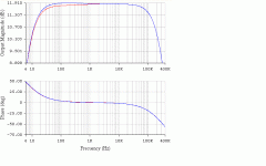
The blue curve corresponds to what You have kindly uploaded.
regards
Attachments
I've been testing and studying this setup for almost a year.
Hi,
You are dull and boring. If you genuinely had something new,
the immensely stupid thing to do would be to come here and
talk about it. * But you don't, but want to pretend you do.
Your just full of smug BS as far as I can tell.
rgds, sreten.
* Chances of anything new are near zero. Nothing much new
in circuit design gets past the 1930's, where the theory did
exceed the devices available, not a problem for theory.
Last edited:
Ditto, SRETEN, ditto. The "problem" is that I keep getting email that says there are more comments in this miserable thread. The forever-hopeful part of me wants to see Smuggenstein just attach his supposedly magnificent advance in the art of passive-component first-order/second-order IIR filter design. So far, mystery steeped in a sauce of obfuscation and pseudo-intellectualism, unerringly without content.
GoatGuy
GoatGuy
It is very easy to believe that one knows everything.
It is much easier to divert the topic thread, when no answers.
It is really difficult and laudable recognize the limitations.
It is even more difficult to contribute positively to a topic.
Only those who have contributed positively to this subject have effectively contributed to enrich it. The rest, I do not care.
Each of you will know which place belongs.
regards
Mooly: Thanks again for your contributions and your efforts. That's a great attitude. It is no accident that you are a moderator.
For those skeptics: This new implementation allows us to lower the cutoff frequencies at the low end (with the current values of capacitors) or, better yet, we can use several times smaller capacitors for the same purpose (with all the advantages this implies, knowing of the problems characteristic of large capacitors). These are the more obvious advantages. If the capacitors are several times smaller, we can think seriously about a possible integration of them.
The less obvious advantage (but not least) is a significant improvement in low frequency distortion. To understand this, we must analyze how the signals are arriving by both inputs of the differential amplifier (pin + and -) on the operational amplifier. That is, we have to analyze how these two signals behave versus frequency. The parcial-transfer function to each of these two inputs (from input signal source to pin +, and from opamp output to pin -) must react in a similar fashion versus frequency, abstracting for a moment of what happens with pin + and - in a linear application.
What has been done is to perform an equalization in both signals so that the difference between them be much more constant with the variation of frequency.
That's all that I can tell you.
regards
Last edited:
Hi,
No we are not. Some of us are utterly bored. Why explore options for
someone based on some totally pretentious claims, that allow the
goalposts to be moved at anytime depending on the information
received, and excuses as to never define where they actually are.
rgds, sreten.
Ditto, SRETEN, ditto. The "problem" is that I keep getting email that says there are more comments in this miserable thread. The forever-hopeful part of me wants to see Smuggenstein just attach his supposedly magnificent advance in the art of passive-component first-order/second-order IIR filter design. So far, mystery steeped in a sauce of obfuscation and pseudo-intellectualism, unerringly without content.
GoatGuy
Another thread notifier I'm afraid guys...
Just to say that at the top of the thread under thread tools is an "unsubscribe from this thread" button
")
If you want to keep posting to the thread then try and keep it constructive.
Hi,
There is nothing unconstructive about saying "somebody has reinvented
the wheel", in this case "bootstrapping", if the circuit works as claimed,
or they don't have anything if it doesn't work as claimed.
The claims about distortion appear to be
"guilding the lily" and don't make any sense.
The only way to lower the high pass frequency is to make the apparent
input impedance higher, and to do that you need to modulate the other
side of the input resistor with a signal similar to the input signal. This
is a doddle with a unity gain stage, with a bootstrap capacitor from the
output. If you have gain then the unity gain point is the inverting input,
and you bootstrap from that point, noting it has higher source impedance
than directly from the output.
What is unconstructive is the obfuscation about something that either
works and is very old, or its "new" and it doesn't work as claimed.
There is a phenomenal arrogance in stating you have come up with
a "new" simple circuit topology when that likelihood is very near zero.
rgds, sreten.
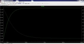
Unity gain bootstrap for a low low pass with a small capacitor :
How to modify the original circuit should be obvious.
There is nothing unconstructive about saying "somebody has reinvented
the wheel", in this case "bootstrapping", if the circuit works as claimed,
or they don't have anything if it doesn't work as claimed.
The claims about distortion appear to be
"guilding the lily" and don't make any sense.
The only way to lower the high pass frequency is to make the apparent
input impedance higher, and to do that you need to modulate the other
side of the input resistor with a signal similar to the input signal. This
is a doddle with a unity gain stage, with a bootstrap capacitor from the
output. If you have gain then the unity gain point is the inverting input,
and you bootstrap from that point, noting it has higher source impedance
than directly from the output.
What is unconstructive is the obfuscation about something that either
works and is very old, or its "new" and it doesn't work as claimed.
There is a phenomenal arrogance in stating you have come up with
a "new" simple circuit topology when that likelihood is very near zero.
rgds, sreten.
Unity gain bootstrap for a low low pass with a small capacitor :
An externally hosted image should be here but it was not working when we last tested it.
How to modify the original circuit should be obvious.
Last edited:
sreten:
My circuit does not look anything like what you have presented.
There are many more variants. Not everything always leads to this bootstrapping technique (which may serve to increase the impedance seen by the signal source) ...
Do you think that this bootstrapping technique is the only way to reach the goal?. The technical horizon is wider than you think.
As an example: Mooly uploaded a proposal that does not necessarily use the bootstrapping technique (and was very close to the targets).
Anyway, thanks for your effort (that's more positive for the whole forum).
regards
sreten:
Here there is no pretense of anything: I have invited you to try to get a particular result in a given circuit, given certain conditions.
Anyone who wants to participate, explains his idea and then we can discuss it. This is very simple.
Also, I do not pretend to redefine the way each of you design their circuits: I only expose the pros and cons of each alternative (uploaded by forum users) when compared with the option that I use, to arrive at the desired results.
If someone finds out what I'm using, congratulations.
If not discovered, also serves: you can always salvage something positive.
regards
SRETEN, I simply don't think that DiegoMJ has any idea how ivory-tower pretentious he's being. I've noted this in other forums, and with people in daily life. They have extraordinary faith in their magnificent achievement, and through scheming and obfuscation, through come-along and super-authoritarian pseudo-mentorship, challenge all those whom they get in audience, to invent or recreate something they barely have the ability to concretely describe. DiegoMJ is such a character, it is clear. Has probably desired his entire life to be so inscrutably superior that all people around him are not peers but subjects.
Paraphrasing his pretention: "I have done it! I challenge you to take this simple looking thing, and using no other components, improve upon it hugely. The results you come up with, I will grade for their authenticity, and I'll keep providing feedback while y'all with my blindfolds on, keep searching with your hands out. Its fun! Its educational! Keep at it me hearties! You're so close to the bucket 'o' gold. (Moves the bucket again...)"
Yes, pretention, stultifying self-absorbed ego, and if anyone unhappy with this analysis cares to remember: No damned diagram Its patent-pending, you know.
Your analysis of impedance-lifting is exactly correct. There are no other solutions that don't topologically rearrange to impedance multiplication if the frequency-response of an input (or other signal-path) capacitor is to be mitigated. Period.
GoatGuy
I have a question
The circuit in post 1 could be duplicated (i.e. two built) and then be fed from a "normal" source such as a CD player etc. Both circuits would in that case operate independently of course.
Can your "new" circuit like-wise be duplicated in the same way and two the "channels" operate independently when fed from a "common" source.
Just a wonderin
This is a great challenge; it's very easy to understand yet very difficult to solve.
Hi,
Really ? How do you know that ? You'd have to know the supposed
solution and your stuff to be any judge of the merits of this thread.
rgds, sreten.
I've already posted how you usually would do it, and it works.
Last edited:
- Status
- Not open for further replies.
- Home
- Amplifiers
- Chip Amps
- Opamp challenge