JMFahey:
The circuit presented by you does not seem in the least to mine.
Also, if you take the trouble to simulate or measure will notice that this circuit does not meet even close to what I can get with my design.
Believe me, I understand you perfectly in the fact that you may be wary of something new.
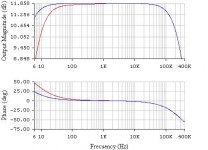
The blue curve corresponds to what you have kindly uploaded.
regards
The circuit presented by you does not seem in the least to mine.
Also, if you take the trouble to simulate or measure will notice that this circuit does not meet even close to what I can get with my design.
Believe me, I understand you perfectly in the fact that you may be wary of something new.
The blue curve corresponds to what you have kindly uploaded.
regards
Attachments
I used the 741 simply to represent an audio amplifier. But you can extend the application to any similar topology (TL071, TL081, etc or even discrete, like the one I'm using). This can be for small signal or power, too.
Laboratory measurements were made with a simple and inexpensive TL081CP.
I know I'm risking a lot in a forum as prestigious as this. And was not the only one in which I presented this challenge. This is my choice for very personal things (which may be irrelevant to the forum, but it is very important to me).
With my greatest respect
I'm intrigued by what you feel you have come up with. I haven't been able to replicate all you claim in particular keeping the voltage gain at around +3.9
By AC coupling the output via the 10 uf you can then use the 10K as a ground reference.......
Have you tested your circuit with non sinusoidal waveforms and deemed it acceptable ?
By AC coupling the output via the 10 uf you can then use the 10K as a ground reference.......
Have you tested your circuit with non sinusoidal waveforms and deemed it acceptable ?
Why is it prohibited to skip components? Wouldn't the possibility to achieve a similar result with less components be an inprovement?
If you can live with inverted phase, you can tidy up the following schematic later. I.e. skip the 100 n cap, use 2,4 k instead of 2 x 1,2 k, 9,31 k or 9,53 k instead of 2 x 4,7 k.

If you can live with inverted phase, you can tidy up the following schematic later. I.e. skip the 100 n cap, use 2,4 k instead of 2 x 1,2 k, 9,31 k or 9,53 k instead of 2 x 4,7 k.
I came up with this as per original requirements although I suspect it isn't what he is after... and its just a bit of fun 
AC coupled input, Yes
Similar HF response, Yes
Voltage gain of 3.92, Yes
Similar input impedance, Yes
Output developed across the 10K, Yes
Same components used, Yes. All the components in the original are used.
No real offset issue, Yes. The 741 isn't perfect here anyway.
Non inverting of overall phase, Yes
Attachments
Why is it prohibited to skip components? Wouldn't the possibility to achieve a similar result with less components be an inprovement?
If you can live with inverted phase, you can tidy up the following schematic later. I.e. skip the 100 n cap, use 2,4 k instead of 2 x 1,2 k, 9,31 k or 9,53 k instead of 2 x 4,7 k.
I think the poster (original) is suffering from delusions and is further insufferably pretentious. A "design" without a "purpose", or with a "secret purpose", and an ill-defined "challenge" ... is delusional and pretentious.
"Power - makes others strive to want something that is kept unachievable" - some wag in 1949.
GoatGuy
Pacificblue:
Close, but suffers three important things:
1) The magnitude, while not as is (it is very close), but the phase is inverted. This could be a minor problem but ...
2) The offset problems have not been considered. This stage can cause problems, if the gain becomes important (to make it more generic).
3) There is an improvement that is not served by that configuration, but I can not disclose yet, because it would give guidelines to find the answer.
The blue curve corresponds to what you have kindly uploaded.
regards
PD: I did not say I was forbidden to skip components.
Attachments
Last edited:
To accomplish this, one has to use the same components shown in Scheme A (referring to quantity, type and value). Not allowed to remove or add components as those shown in Scheme A (you must use the same components, to achieve the objective of this challenge).
Pacificblue:
PD: I did not say I was forbidden to skip components.
Please clarify
In the first post you say all components must be used (not allowed to remove...) and the later post implies you can skip using some parts.Please clarify
Remove: use fewer components that have been shown. Example: if the original scheme employs 8 => implies having used less than 8.
Add: use more components that have been shown. Example: if the original scheme employs 8 => implies having employed more than 8.
There are no restrictions on the order of connection between components. There is complete freedom to connect as you wish.
PD: In the scheme proposed by Pacificblue the input impedance of the circuit is not around 5K9 (in the passband).
regards
Last edited:
OK thanks
I guess we're just going to have to see what you come up with. Extending the LF response by reconfiguring the circuit is easy of course... and does what you ask... but I guess that's not what your getting at.
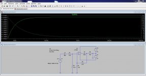
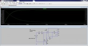
The first simulation here wouldn't work in practice using real parts (although it does work in spice)
The second would work of course but its totally standard and can't be what you are getting at. It does have the added bonus though of decoupling the opamp rails though, which is is a "huge" benefit.
So I guess its over to you to show what you have come up with
(we are all intrigued)
I guess we're just going to have to see what you come up with. Extending the LF response by reconfiguring the circuit is easy of course... and does what you ask... but I guess that's not what your getting at.
The first simulation here wouldn't work in practice using real parts (although it does work in spice)
The second would work of course but its totally standard and can't be what you are getting at. It does have the added bonus though of decoupling the opamp rails though, which is is a "huge" benefit.
So I guess its over to you to show what you have come up with
(we are all intrigued)
Attachments
Mooly:
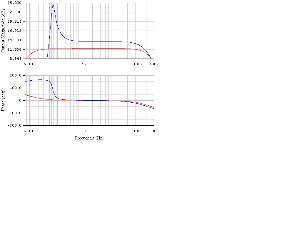
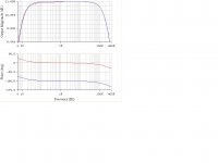
The approach has been quite good, so that you can verify that this is not yet the configuration I'm using, I'll upload a comparison with the diagram on the right you have kindly uploaded. With respect to the other scheme that you have uploaded, it will not be considered by what you said.
Give me time to compare the schemes in terms of other parameters of interest, since both magnitude and phase are only a small part of the story.
The blue curve corresponds to what you have kindly uploaded.
regards
Attachments
Last edited:
The choice of opamp (its input impedance) makes a small difference here to the graphs. I'm just using standard models from the spice library. The 741 has quite a low input impedance (by todays standards).
However, given the relatively low external resistor values, the parameters of the operational amplifier does not substantially affect the low frequency response. The final response at low frequencies is governed mainly by the external components.
The high frequency response is more influenced by the parameters of the operational amplifier, apart from any component in the feedback loop (eg, an external capacitor).
Also, from what I could check on your latest proposal, the offset can be a problem (if the gain grows), unlike the scheme that I use (which lacks this drawback).
Anyway, give me a little more time to expose some additional advantages of my scheme (compared to those proposed).
regards
However, given the relatively low external resistor values, the parameters of the operational amplifier does not substantially affect the low frequency response. The final response at low frequencies is governed mainly by the external components.
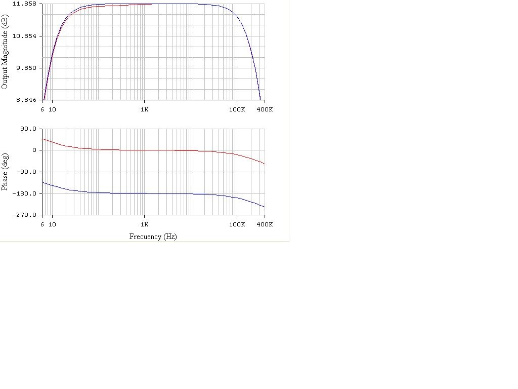
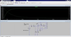
That is what you would expect (its what I would have expected too... give or take) but the reality seems somewhat different. This is the circuit I posted above (#post 31, first picture) but with the 0.1uf shorted. Two different opamps used as shown on the pic.
Attachments
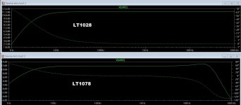
That is what you would expect (its what I would have expected too... give or take) but the reality seems somewhat different. This is the circuit I posted above (#post 31, first picture) but with the 0.1uf shorted. Two different opamps used as shown on the pic.
... but the LF response seems identical to me?
jan
... but the LF response seems identical to me?
jan
Its me going cross eyed looking at it... your right
Mooly:
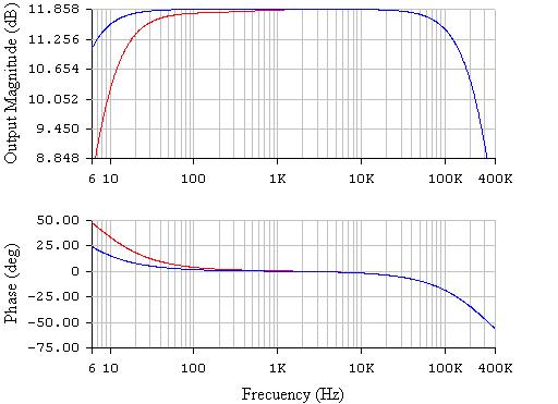
You can superimpose the two curves and add a grid?. I think I see that both curves do not differ at low frequencies (this indicates no dependence of the operational amplifier used). Clearly both curves differ beyond 20 KHz (this indicates that there is dependence of the operational amplifier used).
It seems to be just as I had anticipated you.
Precisely, it was the fact that we can not have big government on the parameters in the high frequency area, which made me look for improvements in the low frequency area, where what defines performance in the low frequencies are mostly external components and no necessarily the op amp.
regards
- Status
- Not open for further replies.
- Home
- Amplifiers
- Chip Amps
- Opamp challenge