Take this one with you too, do they pay well in Holland?
Sorry, too late
")
No you have to pay them (it seems).
This may help Patent It Yourself: Your Step-By-Step Guide to Filing at the U.S. Patent Office - David Pressman - Google Books
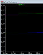
Here another observation, although the 'original' circuit exhibits some offset, my new and improved circuit has 'NO'-offset (see picture). LTspize shows -0.00308642fV (as near to 0V as humanly possible ) (ohhh, and I know why )
) (ohhh, and I know why )Attachments
Last edited:
Dear FdW!
Ad post #100: very good approximation! To use the 0.1µF as bypass C - very clever!
IMHO there exists another optimization option: you could remove the 10kOhm resistor R9 too ...
Regards, Toni
P.S.: Schematics from post # 74 and #75 are already patented - sorry all other out there: you are too late!
P.P.S.: this is my last post in this thread. Closing now browser.
Knowing now that the 10K doesn't figure in it all I can't see a solution. If the input has to be AC coupled, then as I see it pin 3 needs to see 5.9k to ground both to define the input impedance and to set the DC conditions. Bootstrap it in any way and you lose that...
Maybe there is a way to include the supply current in the feedback loop. It seems possible that since there is a high PSSR for uncorrelated signals that this property could be used in reverse somehow. Sort of the reverse of using voltage regulators as audio amps.
In any event, I think I can better define the question that I tried to ask before. When the input signal return is tied to the top of the .1uf cap it fairly well duplicates the original frequency response at that same node in the original circuit where the 10uf cap was installed. I cannot find a good explanation of how that works and I haven't been able to suss out any logical explanation for it myself. I do see some references to capacitance multipliers using op amps, and I'm guessing this is similar, or maybe I'm going down the wrong path. Is there an explanation for this somewhere that someone can point me to?
A well known formula for RC filter calculation is
fc=1/(2*3.1415926*R*C)
So if we use the 10µF capacitor with the input impedance which should be about 5.9 kOhm the -3dB cut off frequency is about 2.67 Hz which does not correspond with the presented graphs from diegomj1973.
My post #75 has an input impedance of about 2.4 kOhm which gives us -3dB at 6.63 Hz. => exactly what all graphs from diego are showing.
Conclusions:
* the 10µF capacitor is not connected at the input stage
* or diegomj1973 measurements are wrong and his circuits input impedance is 2.4kOhm and not 5.9kOhm.
astx:
The reasoning that you have done is correct.
As you have seen, the impedance in the passband is about 5K9 (in my modified circuit). That does not mean that the impedance of 5K9 remains outside the passband.
regards
To all the other people I ask to give me a little more time to go answering them.
I have not seen my schema, yet.
Post #90 tells us that the 10k connects between pin 6 and zero volts which means that the output voltage must be measured on pin 6 to meet the requirement of "the output voltage is developed across the 10k"
No nearer
When connected beween V(out) and Gnd, then it serves no purpose.
diegomj1973; why not remove this resistor? or can you describe it's purpose?
Hi,
The whole point of this allegedly "new" circuit is that it allegedly
allows the reduction of the input coupling capacitor of "standard"
circuits, so anything with 10uF at the input is a non-starter.
Which is not that useful if it needs a large capacitor elsewhere.
The style of this thread indicates to me you are all being led
a merry dance by someone who doesn't really have anything.
rgds, sreten.
OK thanks
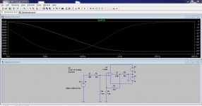
I guess we're just going to have to see what you come up with. Extending the LF response by reconfiguring the circuit is easy of course... and does what you ask... but I guess that's not what your getting at.
The first simulation here wouldn't work in practice using real parts (although it does work in spice)
The second would work of course but its totally standard and can't be what you are getting at. It does have the added bonus though of decoupling the opamp rails though, which is is a "huge" benefit.
So I guess its over to you to show what you have come up with
(we are all intrigued)
I'm getting confused
sorry
Last edited:
Do you know why Mooly's example makes the .1uf cap look like a 10uf? I'd really like some help with that.
Where was that posted? Again confused: You refer to the 100nF used as the output capacitor (that will limit low frequency output voltage swing severely (I think)).
Last edited:
I think everyone understood your position the first time you posted it. The 37th time doesn't add a whole lot.
Do you know why Mooly's example makes the .1uf cap look like a 10uf? I'd really like some help with that.
Do you mean this one, post #31
http://www.diyaudio.com/forums/chip-amps/227787-opamp-challenge-2.html#post3330328
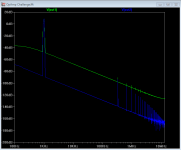
The 0.1 is now included in the feedback loop. Our point of interest is across the 10k and so the feedback keeps this point correct. If you look at the output
of the opamp rather than the notional output terminal of the circuit then the opamp output rises with decreasing frequency to counter the rise in Xc of the cap. The downside is that the circuit will clip easily at low frequency because the output of the opamp has to be so large.
Here's the output of the opamp rather than at the other side of the cap.
Attachments
I think everyone understood your position the first time
you posted it. The 37th time doesn't add a whole lot.
Hi,
Such a childish comment adds nothing.
Address the points in the post or say nothing.
rgds, sreten.
Last edited:
And who says it's connected between Vout and Gnd?Quote:
Originally Posted by Mooly View Post
Post #90 tells us that the 10k connects between pin 6 and zero volts which means that the output voltage must be measured on pin 6 to meet the requirement of "the output voltage is developed across the 10k"
No nearer
When connected beween V(out) and Gnd, then it serves no purpose.
And who says it's connected between Vout and Gnd?
Post #90
If it helps: the 10K resistor is connected directly between pin 6 and 0 volts (in both variants: the common and modified). It may be another value, too: to make it more generic.
Tested with TL071, TL081CP, LM741.
It works in real conditions and simulations.
I had uploaded a video on YouTube that showed a better response at low frequencies. However, I had to delete when I realized the possibilities this could offer myself.
regards
Hi,
I currently amuse myself occasionally by buying toy kits that on the
the box state 3+ (years old), that is true in terms of playing with the
parts, but the real challenge is to use every single part to look like
toy illustrated but without enough instructions / illustrations /
information to be able to do that, and certainly on purpose.
That is the parent bit I guess, and TBH I genuinely assume it
can be done, and if I can't work it out, I'm missing something.
So if some take the same attitude to this "challenge" fair enough.
But I don't, I do know my stuff, and it seems most taken in don't.
rgds, sreten.
Last edited:
So, is there a closure date on this challenge, or can we expect it to go on for ever without the OP's solution ever getting seen?
I certainly wouldn't offer a contribution without some suggestion that I wasn't just *issing in the wind. In fact, I think anyone with a shred of integrity posting such a challenge should have lodged the solution in a sealed envelope with a third party with instructions to open it on a specified date, or earlier if the solution was found, and that anybody taking it up without such a safeguard is misguided. Otherwise, who knows if a solution exists? And even then, it's just a sealed envelope, it could be empty.
I wouldn't have been as outspoken as sreten for reasons I'll leave you to guess, but I'm damned glad somebody has been. There's something about this thread that doesn't really respect the members, whether or not some people are insensitive to it.
Last edited:
- Status
- Not open for further replies.
- Home
- Amplifiers
- Chip Amps
- Opamp challenge