I think I finally figured out my problem from the other night - and of course it was pilot error.
I had started with one of those spice tutorials and set up the circuit, then I copied it and modified the copy such that I could have the two of them running side-by-side, which is really cool. What I didn't understand was that the two labels for "OUT" would be seen as common to each other in the simulation. This was creating some unanticipated results that were confusing the heck out of me.
Once the mystery is solved it's no longer much of a mystery. It's a lot like finally finding a short that creates a whole lot of strange symptoms that don't appear related.
Anyhow, thanks for sticking with me on that and trying to help out. I do appreciate it.
As for whether or not there is a real solution to this challenge, I can't really say for certain. The frequency response curve in OP came from somewhere, that much I am certain of. What its origins are has not been ascertained for certain at this point, that much is true.
We seem to each make a personal choice of whether or not to believe the OP is possible. I just don't have enough knowledge to see any particular set of properties that would make the claims impossible. Instead I can take some amusement in reading the posts where someone says - it's as old as the hills, nothing new here move along; juxtaposed with someone else saying - it cannot be done, it's an utter impossibility; all from the experts here, and sometimes even getting both arguments from the same member. That's entertainment, I don't care who you are.
Well, *there are* many answers, many apparently contradictory and yes , even from the same poster, simply because there are a couple dozen configurations using the same components .... and they will all be different, of course, so that shouldn't surprise you.
Since the OP only answer is "no, that's not the one", the wheel will keep turning.
For some useful purpose?
Don't think so.
Is this some ground-breaking solution to something?
Don't think so.
More important: should we trust the curves posted by the OP?
I think you will by now start guessing my answer:
"Don't think so."
They can't be challenged anyway") , all we have is his word
, all we have is his word
From the way this "challenge" was posted and the followup, I guess the OP is a quite green newbie who installed some simulation software, started throwing parts at it, wondering at the nice curves, changed some configuration, got some new ones, and "thinks" he's discovered something important.
In fact, maybe he even mis installed the Simulation Software or doesn't even know very well how to use it
Of course, to save face now he must carry on this charade.
Does he have any other choice?
He will never post something that will prove him to be a fool, so he will hide behind the "no, it's not that" curtain forever.
Or until he gets a Patent, which he can then post here, which for some strange reason amounts to the same . (never ever).
Since the OP only answer is "no, that's not the one", the wheel will keep turning.
For some useful purpose?
Don't think so.
Is this some ground-breaking solution to something?
Don't think so.
More important: should we trust the curves posted by the OP?
I think you will by now start guessing my answer:
"Don't think so."
They can't be challenged anyway
, all we have is his word From the way this "challenge" was posted and the followup, I guess the OP is a quite green newbie who installed some simulation software, started throwing parts at it, wondering at the nice curves, changed some configuration, got some new ones, and "thinks" he's discovered something important.
In fact, maybe he even mis installed the Simulation Software or doesn't even know very well how to use it
Of course, to save face now he must carry on this charade.
Does he have any other choice?
He will never post something that will prove him to be a fool, so he will hide behind the "no, it's not that" curtain forever.
Or until he gets a Patent, which he can then post here, which for some strange reason amounts to the same
. (never ever).
Last edited:
Personally I have no doubt that whatever the arrangement is, it was figured out independently by several 'tube guys' in the '50s or '60s....
It is probably one of the 4 (at least, certainly more) standard bandpass/highpass filters that you can do with these components to which the OP inadvertently applied a delta-to-Y transformation or viceversa...so that it looks "new". In a way the improvement is a side effect of the limited choice of values, if I may say so. Patenting it...I doubt!
If we get to see the solution it will be, well...obvious. Other than that I'm not denying the entertainment value of this thread, we're all learning something...if we don't take it too seriously.
Edit: The 2 'solutions' that I posted are intended to show what can go wrong: capacitive loading of the source, no DC path to bias the inputs (except the source)...etc.
.It is probably one of the 4 (at least, certainly more) standard bandpass/highpass filters that you can do with these components to which the OP inadvertently applied a delta-to-Y transformation or viceversa...so that it looks "new". In a way the improvement is a side effect of the limited choice of values, if I may say so. Patenting it...I doubt!
If we get to see the solution it will be, well...obvious. Other than that I'm not denying the entertainment value of this thread, we're all learning something
...if we don't take it too seriously.Edit: The 2 'solutions' that I posted are intended to show what can go wrong: capacitive loading of the source, no DC path to bias the inputs (except the source)...etc.
Last edited:
I've read everyones postings and offer the following,
That if someone posted the circuit diegomj1973 is using, that he would at least be gracious enough to say so.
Personally, I haven't been able to come up with a configuration that meets all the requirements, however those requirements it seems were not in themselves completely stated in post #1. I'm thinking particularly about the point of being able to duplicate the circuit and have them operate independently while using "common" grounds for the source. That was something I asked. And I admit I can't see a solution while keeping to all the parameters.
To everyone that says this will be just another variation of some well known technique... the answer to that is obvious... just post your solution. Surely that would answer the argument that diegomj1973 will always say "no that's not the answer". Whether it be a circuit that isn't practical, an obvious configuration that everyone would recognise, or one that only runs in simulation... post it.
Where do I stand in all this...
I took the thread at face value as a simple "challenge". I thought it might be do-able (whether or not it was radical or unusual or "patentable" was beside the point for me) and I actually came up with a solution that "matched" very very closely the original objectives regarding gain and phase). Having further looked at the components available and all the requirements needed I personally now don't think those objectives can be met (that's my personal view).
The first post (which has to be taken at face value) implies that the patent procedure has already started and so that chain of events precludes divulging the details. That's fair enough from diegomj1973's perspective.
However... that begs the very fair question... why thow this idea to a public forum if the patent process has started ? and also, is it in the forums interests to now keep this thread open ?
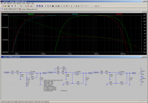
To get close to the frequency response curves like in post #1 you have to develop a circuit like the middle one. Then start a "opamp challenge" and do not allow people to use other components like the left one. They only will get close to the frequency response curves but never will get the correct values. If the challenge would have been something like:
Regards, toni
"change the left circuit to reach the response curves as shown and you are allowed to add or change some values"
it would have been a fair contest and a nice LTSpice learning game. But diego's "opamp challenge" is definitely a farce and disrespect towards all other forum members. I understand sreten's and other members anger...
Regards, toni
Attachments

- Status
- Not open for further replies.