The LM1036 a good all-in-one chip for 'my first tone control project' however it's signal handing is poor, for example, it's max input of 1.6V rms is easily exceeded by a typical modern CD player output (CDs normally give 2Vrms max). also distortion and noise figures are poor even at it's rated level by modern standards. It is in fact a 1970's chip designed to go with partnering Toshiba remote control ICs (no longer available IIRC) that gave the required analogue control outputs...
.... I wouldn't recommed it myself for new and/or quality designs, but don't let me stop you if you want to give it a try.
BTW, Philips do a similar chip - a TDA1524 which has much better signal handling esp. if you apply feedback network mentioned on P.4 of the datasheet...
http://www.google.co.uk/url?sa=t&rc...07_1zvLeoF_TMYg&bvm=bv.42553238,d.d2k&cad=rja
Last edited:
Sorry to leave this thread hanging for so long. I had an online class that took up a good bit of my time the last month. Finally, after a couple frustrating mishaps and some replacement parts, I have both channels of the amp together and everything appears to be working properly. It sounds quite nice so far. I'm looking for an enclosure for it now.
I actually think I've decided to leave out the tone section... at least for now. I breadboarded the tone section and I wasn't really happy with how it sounded. I need to play with it a little more, but it just wasn't sounding right. I'll leave a little space in the enclosure in case I get it working properly and want to add it later. I found a software equalizer that's giving me much better control and sound than the tone control in the amp would give me anyway. So I'm thinking I'm going to keep the amp simple, and use the software EQ. Or maybe I'll build an external tone control instead later if needed.
I'll post final pictures once I get it in a case and clean up the grounding/wiring and all.
Thanks again to Mooly and blu_glo and others for all the help!
Attachments
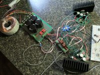
Thats a nice beefy supply board and love the star earthing point!
Curious to hear you couldn't get the tone control to sound right, was to too bright or dull or...?
Maybe it needs a more stable base than breadboard; there's a lot to go wrong in the tone section!
I was going to make a copy the tone/buffer design for myself with the op-amps you suggested but being a natural "bottlehead" decided I'd rather do it with some mini valves (tubes) as I have 6112 dual triodes kicking around, need 1 triode from each to substitute for each op-amp. Heater supply can be derived from the main transformer windings and need only 80-90V dc HT which can come from a voltage "quadrupler" to the same windings. I'll see if I can post some outcome soon. Recently got my LM3875 Sperry gainclone boards working a treat, to go with this preamp.
Last edited:
Thats a nice beefy supply board and love the star earthing point!
Curious to hear you couldn't get the tone control to sound right, was to too bright or dull or...?
Maybe it needs a more stable base than breadboard; there's a lot to go wrong in the tone section!
I was going to make a copy the tone/buffer design for myself with the op-amps you suggested but being a natural "bottlehead" decided I'd rather do it with some mini valves (tubes) as I have 6112 dual triodes kicking around, need 1 triode from each to substitute for each op-amp. Heater supply can be derived from the main transformer windings and need only 80-90V dc HT which can come from a voltage "quadrupler" to the same windings. I'll see if I can post some outcome soon. Recently got my LM3875 Sperry gainclone boards working a treat, to go with this preamp.
Well, I think you might be right about it needing to be more stable than the breadboard. It was finicky on the breadboard. But I think it overall just didn't sound very nice. It significantly colored the signal.
The main problem seemed to be that I couldn't find a middle/neutral point that sounded anything like the straight signal. Putting the pots (linear) in the middle position didn't sound neutral at all. Moving them around, I still couldn't find a spot that felt right. It did sound kind of dull on the highs, but when I turned the treble up, it got harsh, not clear. Maybe something sounded strange with the mids too. The low certainly could add a BIG bass boost, which wasn't bad. I think it was mainly the highs and mids that just did not sound right. Muddy and weird might be the best way to describe it...
Sorry I know that description probably isn't real helpful, but I know I don't want to put it in my amp, at least yet. I think I'm going to build it on a board anyway since I have all the parts and see how it goes. Maybe it will sound better then. I'm leaving room in my enclosure if I want to add it later, or maybe I'll just make an external tone control so I can use it with other projects too.
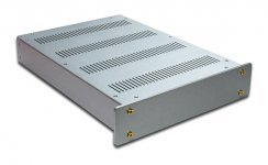
Attached is the enclosure I ordered. Will probably take a couple weeks to come from china. Really anxious to get it finished... so close.
Attachments
Pleased to see you have it all working... its looking good")
Got the case and put the amp together (without volume or tone for now). I'm really happy with the case. I'll post some other pictures later.
I've got one issue that's confusing me. When I hook up a MP3 player as the source, it works perfectly. No DC offset or pops, and only gets warm. But when I hook it up to my DAC/Computer as the source, the DC offset jumps to ~46mv and when I power it on, it pushes the speakers out some for a second before settling back. It also give some noise at turn off and gets much much hotter. Obviously something isn't right when hooked up to a source plugged into the wall as well.
At first I didn't include the 100ohm resistor between 0v and earth. When I add the resistor, the offset drops to ~4mv. If I remove any connection between 0v and earth, offset drops back to 0mv. So I'm guessing there's some sort of grounding issue.
Maybe I'm not making the earth connection from the right place? Right now it's connecting from between the rectifier diodes. Should I be connecting it from the power star ground? Even though the 100ohm resistor dropped the offset to ~4mv, I'm thinking that the source should not be changing the offset at all. So I'm wondering if there's an issue elsewhere in the grounding.
Thoughts? Hopefully I explained that right. Thanks for the help.
Attachments
Maybe I'm not making the earth connection from the right place? Right now it's connecting from between the rectifier diodes. Should I be connecting it from the power star ground? Even though the 100ohm resistor dropped the offset to ~4mv, I'm thinking that the source should not be changing the offset at all. So I'm wondering if there's an issue elsewhere in the grounding.
Thoughts? Hopefully I explained that right. Thanks for the help.[/QUOTE]
Hi,
Looking at your picture, can you clarify:
Is your star earth connected to the chassis?
Is the chassis earthed?
It is a grounding issue and I cannot quite see whats going on from the photo. Good work though!
Si.
Thoughts? Hopefully I explained that right. Thanks for the help.[/QUOTE]
Hi,
Looking at your picture, can you clarify:
Is your star earth connected to the chassis?
Is the chassis earthed?
It is a grounding issue and I cannot quite see whats going on from the photo. Good work though!
Si.
Last edited:
That looks a really neat job
Problems like you describe can be hard to track down. Are the input sockets electrically isolated from the case ? They should be.
Without being too specific the case should be connected to mains safety earth. That goes without saying for safety. The amp grounds (and by that the star ground) can connect to the case via a low value resistor. (I don't want to give you wrong info because every amp build is different in the way it has been wired).
If the problem occurs because the source equipment is grounded then I would look at something like I've mentioned above to break the loop. Yet I see you have a low value resistor and the problem improves when its disconnected.
Other possibilities (not very likely having reread your post) are that the DAC/PC is noisy (as in assymetrical HF noise) and that is causing the issue without it having anything to do with grounding. You would really need to scope the DAC output and see what it look like.
Did I ever post a link to this.
http://www.diyaudio.com/forums/soli...-lin-topology-nfb-tappings-2.html#post1624677
It might give you some insight into what goes on with grounding.
Oh also, Make sure the bolt through the transformer CANNOT touch the lid because if it does, it in conjunction with your case becomes a shorted turn resulting in hot and/or prematurely expired transformer!!
Si.
Interesting, didn't know this. The bolt does touch the top of the case. I'll cut it down. Thanks!
Yep, it's an often-missed princple by beginners and experts alike - somewhere in this posts a while back I saw a major manufacturer had missed this error!!
And yes, I did the same mistake, too back in the day, building my first amp with "toroidals", for a friend's party - couldn't undertstand why connecting an earth to the top of the transformer bolt (the base was already earthed) resulted in a large spark....
And yes, I did the same mistake, too back in the day, building my first amp with "toroidals", for a friend's party - couldn't undertstand why connecting an earth to the top of the transformer bolt (the base was already earthed) resulted in a large spark....
Hi,
Looking at your picture, can you clarify:
Is your star earth connected to the chassis?
Is the chassis earthed?
It is a grounding issue and I cannot quite see whats going on from the photo. Good work though!
Si.
That looks a really neat job
Problems like you describe can be hard to track down. Are the input sockets electrically isolated from the case ? They should be.
Without being too specific the case should be connected to mains safety earth. That goes without saying for safety. The amp grounds (and by that the star ground) can connect to the case via a low value resistor. (I don't want to give you wrong info because every amp build is different in the way it has been wired).
If the problem occurs because the source equipment is grounded then I would look at something like I've mentioned above to break the loop. Yet I see you have a low value resistor and the problem improves when its disconnected.
Other possibilities (not very likely having reread your post) are that the DAC/PC is noisy (as in assymetrical HF noise) and that is causing the issue without it having anything to do with grounding. You would really need to scope the DAC output and see what it look like.
Did I ever post a link to this.
http://www.diyaudio.com/forums/soli...-lin-topology-nfb-tappings-2.html#post1624677
It might give you some insight into what goes on with grounding.
The "signal star ground" and the "power star ground" are both isolated from the case and are connected together via a 10 ohm resistor. The input jacks are isolated from the case as well.
The chassis is earth grounded by the screw in the bottom right. The green wire coming from the power supply board connecting that same screw is the only amp connection to earth ground.
Well what I do in my amplifiers might differ from "conventional wisdom" yet I have no problems with hum or noise. However, I'm a bit purplexed by your mention of "DC offset" is this just caused because there's hum introducing a slight, possibly audible, signal in the output. N.B. a severly distorted wave e.g. 50Hz hum can inherently have a significant residual DC offset!
Here's my practice:
1. Earth case directly to Mains Earth connection on IEC socket. (Most important - for safety), as Mooly has also taken care to point out!
2. 0V line to earth/chassis by your 20-100 ohm resistor, usually at the INPUT SOCKETS. No Other connections to earth OR chassis at all.
3. Stitch together left and right channel 0V at the INPUTS and possibly (may not be so critical) also at regular intervals throughout your particular design up to the physical inputs on the power amplifiers. (I find this is as far as necessary in all my builds - do not stitch together the two speaker grounds - thats just a step too far!) This reduces induced hum loops in earth as you are only using one transformer between both channels.
Last edited:
Yep, it's an often-missed princple by beginners and experts alike - somewhere in this posts a while back I saw a major manufacturer had missed this error!!
And yes, I did the same mistake, too back in the day, building my first amp with "toroidals", for a friend's party - couldn't undertstand why connecting an earth to the top of the transformer bolt (the base was already earthed) resulted in a large spark....
That would have certainly confused me too. In my case, I never saw any sparks when taking the lid off or anything. I suspect that's because of the coating or anodizing of the aluminum, so it's probably not actually making a solid connection between the bolt and the lid, but I'll trim it down just to be safe!
That would have certainly confused me too. In my case, I never saw any sparks when taking the lid off or anything. I suspect that's because of the coating or anodizing of the aluminum, so it's probably not actually making a solid connection between the bolt and the lid, but I'll trim it down just to be safe!
"safe" is certainly your concern. Melting transformers are not a good idea..... Yes, anodizing does insulate but you can't really be taking the chance!
Well what I do in my amplifiers might differ from "conventional wisdom" yet I have no problems with hum or noise. However, I'm a bit purplexed by your mention of "DC offset" is this just caused because there's hum introducing a slight, possibly audible, signal in the output. N.B. a severly distorted wave e.g. 50Hz hum can inherently have a significant residual DC offset!
Here's my practice:
1. Earth case directly to Mains Earth connection on IEC socket. (Most important - for safety), as Mooly has also taken care to point out!
2. 0V line to earth/chassis by your 20-100 ohm resistor, usually at the INPUT SOCKETS. No Other connections to earth OR chassis at all.
3. Stitch together left and right channel 0V at the INPUTS and possibly (may not be so critical) also at regular intervals throughout your particular design up to the physical inputs on the power amplifiers. (I find this is as far as necessary in all my builds - do not stitch together the two speaker grounds - thats just a step too far!) This reduces induced hum loops in earth as you are only using one transformer between both channels.
The case is safely connected to IEC earth, rest assured
I'm not getting any audible hum. The amp sounded ok, I just noticed the speakers getting pushed out with turn on and the noise at turn off and checked the DC offset to discover it was ~46mv instead of ~0mv. I also noticed it was getting hotter than when testing with just an MP3 player. That's how I discovered something was wrong when connected to DAC. I watched the offset go up as soon as i connected an RCA to the DAC. I then experimented with the grounding as stated earlier.
I'm a little confused by #2. When you say INPUT SOCKETS are only connection to ground, which sockets are you referring to? I only have one connection to earth ground currently (from between the PS diodes, 0v, to earth ground).
I have the two RCA inputs' grounds tied together and then one wire going to the "signal star ground."
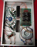
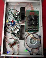
I labelled my image:
Blue Arrow: Isolated RCA input jacks. Shield/Grounds tied together with one wire going to signal star ground. L and R going to amp inputs.
Green Arrow: Earth/Chassis ground. Connected to IEC earth. The green wire connects to 0v on PS board, this is the only connection to earth currently.
Red Arrow: Isolated "Power star ground" Holds grounds related to +/- supply and speaker -.
Yellow Arrow: Isolated "Signal star ground" Holds L and R signal grounds from board, as well as single ground from RCA inputs.
Attachments
That looks a really neat job
Did I ever post a link to this.
http://www.diyaudio.com/forums/soli...-lin-topology-nfb-tappings-2.html#post1624677
It might give you some insight into what goes on with grounding.
You did show me this link a while back, and I read through it. I looked at it again last night. I'll look through it again.
You did show me this link a while back, and I read through it. I looked at it again last night. I'll look through it again.
Reading again, I believe I have followed the advice of the thread in my design and layout except for taking the earth ground from the power star ground. I tried that tonight, but it had the same effect as before. I'm still getting about 4mv offset with the 100ohm resistor while plugged into my DAC (~46mv without resistor). It drops to 0mv if I lift all amp earth ground.
At 4mv with the 100ohm resistor, it didn't seem to pop or push the speaker out at turn on, at least not to a noticeable extent. Is the 4mv is negligible at this point? I just don't get why it's doing it, and don't want to run into any problems down the road if that resistor is just a bandaid fix to a bigger problem.
I would guess not, but could not having a volume control have anything to do with it?
4 mv offset is negligible. Even if you work to 100mv the power dissipation in an 8 ohm load is still only 0.00125 watts. Now that won't heat anything, speaker or amp alike. It would represent only 12.5 ma "extra" current in the output stage.
No volume control ?
Why don't you try (just as a test) a simple R/C filter on each input. Be drastic, try something like a series 10K and 1nf to ground and see if that stops the problem. A filter like that would be audible but might give a clue.
No volume control ?
Why don't you try (just as a test) a simple R/C filter on each input. Be drastic, try something like a series 10K and 1nf to ground and see if that stops the problem. A filter like that would be audible but might give a clue.
2. 0V line to earth/chassis by your 20-100 ohm resistor, usually at the INPUT SOCKETS. No Other connections to earth OR chassis at all.
Sorry - to clarify, no other connections between 0V and earth/chassis at all!
Mooly's idea of input decoupling capacitors opon each input is also a very good point.
Best regards,
Si.
- Status
- This old topic is closed. If you want to reopen this topic, contact a moderator using the "Report Post" button.
- Home
- Amplifiers
- Chip Amps
- LM3886 GC with LM4562 tone control