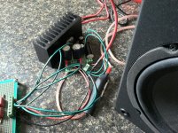
- Thats an interesting shape for the power amp pcb??
It's because the lm3886 pins aren't the same spacing as the board I'm using. But if i turn the chip 45 degrees, they fit perfectly (fortunately!). So i just cut off that side. Actually worked out well for part placement anyway.
I have one amp board almost completed. Once I get that one done, I'll test it to make sure all is well before building the second.
Need to go to the store to get parts for the light bulb tester.
After a very busy week, I finally had a chance to test the first channel and it appears to be a success! It seems to work perfectly so far. It's amazingly quiet, even with messy test wiring/grounding. I can only hear the faintest hiss from the amp with my ear right against the speaker. On to the second channel!
Again, thanks to all who helped me out on this, I'm excited to get this completed.
Again, thanks to all who helped me out on this, I'm excited to get this completed.
Attachments
After a very busy week, I finally had a chance to test the first channel and it appears to be a success! It seems to work perfectly so far. It's amazingly quiet, even with messy test wiring/grounding. I can only hear the faintest hiss from the amp with my ear right against the speaker. On to the second channel!
Again, thanks to all who helped me out on this, I'm excited to get this completed.
Oh, and I'm getting only -1.6mv of dc offset on the output. That seems about right, no?
Oh, and I'm getting only -1.6mv of dc offset on the output. That seems about right, no?
if you kept the input and feedback resistors the same there's no reason for it not to be so low, if you see what I mean....
Anyhow, congrats are in order
 for getting at least half of it working! good luck with the 2nd channel.....
Last edited:
if you kept the input and feedback resistors the same there's no reason for it not to be so low, if you see what I mean....
Anyhow, congrats are in order
Well, I had a feeling things were going TOO well for me... and murphy's law stepped in today. In a moment of pure stupidity, I reversed the +/- rails to my amp board and got some nice smoke and pops from the capacitors... Fortunately nothing was hooked up to the output except my multimeter, as it read over 30v. I'll have to order some replacement parts now and rebuild that board... any idea on whether the lm3886 can take reversed voltage and survive?
I did get the second channel built yesterday, but when I tested it, I was getting some strange DC offset readings. As the amp powers on, there's a small spike in DC offset, but it settles down to 0v. Then when powering off, it remains very low for about 3 or 4 seconds, then suddenly jumps up to -4v. It slowly goes down from there. It was built pretty much identical to the first channel, and I've triple checked the wiring. So I'm a bit confused as to why this is happening. While powered on and 0v dc offset, I hooked up a speaker and it sounds great, like the other board. But I haven't dared leave it plugged in when powering off lest the speaker get hit with -4v.
Any thoughts on what could suddenly cause such a spike of DC offset on power off, but it reads 0v while powered on? I immediately started looking at the 3886's mute function (Rm and Cm on my schematic), but everything appears correct and matches the other (now dead) channel. So I'm confused.
The offset might not be so bad with a load (try it with a 10 ohm or something). Amplifiers of all kinds can do strange things as the rails collapse and the real answer is always to provide a simple switched speaker delay, 4 volts won't harm the speaker but is would spoil the "user experience" of such an amplifier. Try it with the dummy load.
For the channel that saw reversed supply, I wouldn't use the LM3886 whether or not it appeared functional. It's just not worth the risk later down the line.
For the channel that saw reversed supply, I wouldn't use the LM3886 whether or not it appeared functional. It's just not worth the risk later down the line.
I was going to post answer when I got into work (typing on my mobile on a train is a bit of a hit and miss affair) .... However I see Mooly has replied - with exactly the same answers I'd have given!
However in addition I went to check the datasheet because I had suspicion this device had more than one ground - it doesn't. But, there ARE pins with NC written by them Check there are no shorts (solder or copper whisks) to ANY of these pins sometimes NC does not necessarily mean "no INTERNAL connection" and you can get odd behaviour if they ARE connected to anything.....
However in addition I went to check the datasheet because I had suspicion this device had more than one ground - it doesn't. But, there ARE pins with NC written by them Check there are no shorts (solder or copper whisks) to ANY of these pins sometimes NC does not necessarily mean "no INTERNAL connection" and you can get odd behaviour if they ARE connected to anything.....
Last edited:


The offset might not be so bad with a load (try it with a 10 ohm or something). Amplifiers of all kinds can do strange things as the rails collapse and the real answer is always to provide a simple switched speaker delay, 4 volts won't harm the speaker but is would spoil the "user experience" of such an amplifier. Try it with the dummy load.
For the channel that saw reversed supply, I wouldn't use the LM3886 whether or not it appeared functional. It's just not worth the risk later down the line.
I was going to post answer when I got into work (typing on my mobile on a train is a bit of a hit and miss affair) .... However I see Mooly has replied - with exactly the same answers I'd have given!
However in addition I went to check the datasheet because I had suspicion this device had more than one ground - it doesn't. But, there ARE pins with NC written by them Check there are no shorts (solder or copper whisks) to ANY of these pins sometimes NC does not necessarily mean "no INTERNAL connection" and you can get odd behaviour if they ARE connected to anything.....
Great, thank you both. I'll place an order for some new parts today. Heading out of town for the week, so I'll have to wait until next week to get back to it.
I'll double check the NC pins. Will a 10ohm wirewound resistor suffice for a dummy load? 5-10watt?
I am personaly collecting the bits for a similar project; but 3 way tone control and probably 6 inputs or 5 and phono.
Cool, I'd like to see what you put together when you do.
my 4 dummy loads consists of 8 x 1 ohm 25W wirewound resistors (from an ebay job lot of 50) connected in series and mounted in a metal case with 4mm banana plugs. Those are good for 200W continuous! You could do the same with 8 off 1 ohm aluminium clad type resistors mounted on a spare (!) heatsink....
my 4 dummy loads consists of 8 x 1 ohm 25W wirewound resistors (from an ebay job lot of 50) connected in series and mounted in a metal case with 4mm banana plugs. Those are good for 200W continuous! You could do the same with 8 off 1 ohm aluminium clad type resistors mounted on a spare (!) heatsink....
Putting part order together now for everything... looks like I can get 2ohm 15w's for a good price. So I could do 4 of those for 8ohm 60w.
10 ohm (5 or 10) watt is plenty for this. Even a 1 watt carbon would be OK just as a test.
Ah, maybe I'll stick with my original plan then since that will be cheaper and I'm not testing at full power.
If we're just testing for the offset problem at switch off then the 1 watt is fine. If you have thoughts of testing the amp with test tones then you need something far more substantial of course.
Got it. At this time, I'm just looking to test the offset. Thanks!
- Status
- This old topic is closed. If you want to reopen this topic, contact a moderator using the "Report Post" button.
- Home
- Amplifiers
- Chip Amps
- LM3886 GC with LM4562 tone control