Use Dr Cherry tapping point for the NFB back to the -IN input.
That adds an extra pole of attenuation for RF injected into the speaker terminal.
Yes you could do. I think you mean taking the feedback from the other end of the 10 ohm in the network.
Tbh it's an area of design I have never really looked into in great detail.
'gis a clue .... who/whats Dr. Cherry???
Dr/ Professor ? Edward Cherry. I couldn't just turn up anything easily readable for you.
The resistor and cap to ground is a different thing altogether really. Many amps need those to ensure stability with no load (speakers) connected. Its a must have.
The output coil isn't always normally needed in practice. Its there to prevent small capacitive loads from causing instability... such as the long speaker wires blu_glo mentions. The 10 ohm across the coil damps any "ringing" caused when squarewave testing the amp. The coil isn't critical in value, just make sure its air spaced (not wound on a magnetic former) and of reasonably thick wire.
The latest diagram you have posted is a "single rail" configuration. YesAs long as you appreciate the differences there.
Thanks. I'll be sure to include the resistor and cap in my plans.
I am aware that the last schematic is a single rail. Only looking at it for the optional components, still planning the dual supply.
Input impedance of an integrated amplifier is usually 10-47 K ohms; its so it doesn't unduly load equipment connected to it such as CD players etc.
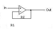
See attached; it seems all the opamps you specify are unity gain stable so hould be ok, so it's up to you which to use or put a socket and choose afterwards! Make R1 = R2 in attached circuit the other resistor not really needed in audio (short "+ input" to 0V) but if you insist, when R1 = R2, R3= 0.5 x R1 (or R2!)
Suggested values R1 and R2 = 22K R3 if insisted apon, 10K is quite close enough.
Thanks for this. I hope to actually learn what each of these elements do while designing/building this amp.
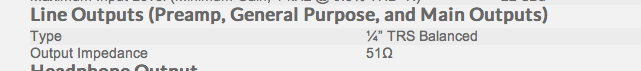
While doing some reading on buffers, I noticed this is an inverting buffer. Is there a benefit over a non-inverting buffer? Also, R1 sets the input impedance, correct? The manual for my firewire interface that will feed the amp says it has an output impedance of 51k, is 22k an ok value to match my source? I do want the amp to be compatible with other sources as well, but for now the main source will be the firewire interface.
I also found some schematics with unity buffers on the input. Is there any benefit or negative to using a unity buffer here? If i understand properly, the unity buffer provides very high input impedance, would that be a better fit here?
Thanks again.
Attachments
Thanks for this. I hope to actually learn what each of these elements do while designing/building this amp.
While doing some reading on buffers, I noticed this is an inverting buffer. Is there a benefit over a non-inverting buffer? Also, R1 sets the input impedance, correct? The manual for my firewire interface that will feed the amp says it has an output impedance of 51k, is 22k an ok value to match my source? I do want the amp to be compatible with other sources as well, but for now the main source will be the firewire interface.
I also found some schematics with unity buffers on the input. Is there any benefit or negative to using a unity buffer here? If i understand properly, the unity buffer provides very high input impedance, would that be a better fit here?
Thanks again.
There is supposed to be a slight reduction in distortion using the inverting buffer due to it's virtual earth mode of operating. However that wasn't the primary reason I chose it! I actually chose it because the tone control is also inverting so I restored the "absolute phase" for you. It is not important, but some swear they can hear a difference and I would build my circuit this way, if only for "tidyness".
Yes R1 sets the input impedance. I'm surprised the firewire interface says output impedance is 51K? Does it mean its SUITED for input impedances of 51K?? Can you please check and copy the exact wording? Most designers worth their salt make output impedances as low as possible for driving reasonably long cable runs etc.....
You can freely use unity buffer if you're not fussed about the signal inversion from the tone control mentioned above. In all non-inverting buffers make sure the + input has a resistor to 0V normally chosen to set your desired input impedance.....
That makes perfect sense. I'm all for being tidy and will go with your advice of using the inverting buffer. Thank you.
I realized that I misspoke and said 51k and not 51ohms for the output impedance. So I realize now there shouldn't be any issue there!
I'm putting together a full schematic and will post in the next day or so hopefully.
Attachments
Last edited:
That makes perfect sense. I'm all for being tidy and will go with your advice of using the inverting buffer. Thank you.
I realized that I misspoke and said 51k and not 51ohms for the output impedance. So I realize now there shouldn't be any issue there!
I'm putting together a full schematic and will post in the next day or so hopefully.
Oh, thanks, I thought madness had consumed all if manufacturers had started issuing equipment with such high output impedances!!!
Yes, 50 ohms or thereabouts is much more what I'd expect.
Would like to see how you get on with that schematic, btw what schematic package are you using?
Oh, thanks, I thought madness had consumed all if manufacturers had started issuing equipment with such high output impedances!!!
Yes, 50 ohms or thereabouts is much more what I'd expect.
Would like to see how you get on with that schematic, btw what schematic package are you using?
I'm just laying it out in adobe illustrator (I'm a graphic designer after all)
Here's a question, would it be better to put the volume pot before the buffer or right before the lm3886 (after tone)? If i put the pot at the beginning, how does that play with the inverting buffer resistors? Also, if pot is at the beginning, should I keep the buffer in line when the tone is bypassed, or would it be better to bypass the buffer and tone altogether?
buffer-tone-volume-power amp, in that order. make sure suitable dc blocking caps on input and output of volume control.
you would want to bypass buffer and tone and if you make volume control 22K then input impedance still stays the same
are you doing switched inputs too?
I thought about having multiple inputs, but i think i'm just doing one for the time being. Maybe a future upgrade.
buffer-tone-volume-power amp, in that order. make sure suitable dc blocking caps on input and output of volume control.
you would want to bypass buffer and tone and if you make volume control 22K then input impedance still stays the same
So caps on both sides of the pot? No caps in front of the buffer?
So caps on both sides of the pot? No caps in front of the buffer?
yes caps on input and between all stages.
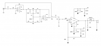
Ok, here's my first attempt at putting it all together. I'm sure I have errors, still working on it. Working on labeling too.
Am I on the right track?
Also, I've noticed that in some of the schematics I've been looking at there appear to be filters along the signal path. Like a resistor and capacitor in parallel to ground. Are these needed and where?
Am I on the right track?
Also, I've noticed that in some of the schematics I've been looking at there appear to be filters along the signal path. Like a resistor and capacitor in parallel to ground. Are these needed and where?
Attachments
Ok, here's my first attempt at putting it all together. I'm sure I have errors, still working on it. Working on labeling too.
Am I on the right track?
Also, I've noticed that in some of the schematics I've been looking at there appear to be filters along the signal path. Like a resistor and capacitor in parallel to ground. Are these needed and where?
I would put a DC blocking capacitor between buffer and tone control stages. Ditto after the volume control.
Not putting a capacitor on the 680 ohm feedback ground of the power amp may cause a small amount of DC offset on the speaker output. This may or may not be significant.
Generally speaking a series (in the signal path) 1K resistor followed by ~ 220pF cap from signal to ground might be unsed on inputs from the outside world, to help prevent RF getting in.
The Preamp part as it stands has no gain. This means this design may work quieter at a given volume level than you'd normally expect. - It's not critcal - but a gain of approx. 4x will correct this. This is easily implemented by using a 82K resistor in the feedback loop of your buffer cirrcuit. (second resistor in from the left!!)
Yes you could do. I think you mean taking the feedback from the other end of the 10 ohm in the network.
Tbh it's an area of design I have never really looked into in great detail.
Wouldn't that likely lengthen the NFB loop quite a bit? I think the data sheet says to keep it as short as possible. Seems like I've seen many solder the resistor right to the pins of the chip to keep it as short as possible.
I would put a DC blocking capacitor between buffer and tone control stages. Ditto after the volume control.
Not putting a capacitor on the 680 ohm feedback ground of the power amp may cause a small amount of DC offset on the speaker output. This may or may not be significant.
Generally speaking a series (in the signal path) 1K resistor followed by ~ 220pF cap from signal to ground might be unsed on inputs from the outside world, to help prevent RF getting in.
The Preamp part as it stands has no gain. This means this design may work quieter at a given volume level than you'd normally expect. - It's not critcal - but a gain of approx. 4x will correct this. This is easily implemented by using a 82K resistor in the feedback loop of your buffer cirrcuit. (second resistor in from the left!!)
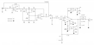
Updated plans attached.
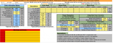
Fortunately, I found the Overture_Design_Guide15.xls file online that really helped out in picking values for the amp section. Correct me if I'm wrong, but the values I have now should work well with my line level source, gain being at 21 and 1.2v input before distortion.
You mentioned adding 4x gain at the buffer, is that still needed? Wouldn't that then make the volume change when switching tone on and off? Or was that suggestion to compensate for some volume loss in the tone section?
Have you found an RF filter on the signal input is usually necessary?
I think the last thing is how to calculate the values for C1, C2, and C3. What formula should be used?
Thanks!
Attachments
Wouldn't that likely lengthen the NFB loop quite a bit? I think the data sheet says to keep it as short as possible. Seems like I've seen many solder the resistor right to the pins of the chip to keep it as short as possible.
The "output end" of the chain (the 10 ohm or 2.7 ohm in your new diagram) is at low impedance and unaffected by whats going on around it and any extra PCB length. It is the inputs of the chip that would be sensitive to extra length and the risk that brings of stray pickup. I wouldn't like to say yay or nay to the technique without verifying it and designing a suitable PCB to match. Stick to what you have drawn.
The times 4 buffer would bring a huge gain change as you say.
C1 and C2 (C3 ???? in the tone control) The inverting buffer (in the tone stage) has an input impedance determined by the 20K. So that determines how big C1 has to be and that in turn is determined by you and what you deem a suitable cut off point. Typically a designer would work to <1Hz for these. So that implies at least 10uf. Why not make the 20k's bigger ? Say 180K. That brings the added bonus of a higher input impedance too and allows a 1uf to be used. C2 needs to be bigger as it drives the low impedance tone network. I would use a 100uf electrolytic here. There is no right and wrong in all this. They are just choices. The 1k and 33uf in the power amp come in at around 5Hz (which is fine for the final power amp stage)
Just spotted an error... The 2 uf cap in the power amp. You need a 20K (or 19 to be correct) to ground from this cap. The pin is floating at DC otherwise and the amp can not establish its DC conditions.
Updated plans attached.
Fortunately, I found the Overture_Design_Guide15.xls file online that really helped out in picking values for the amp section. Correct me if I'm wrong, but the values I have now should work well with my line level source, gain being at 21 and 1.2v input before distortion.
You mentioned adding 4x gain at the buffer, is that still needed? Wouldn't that then make the volume change when switching tone on and off? Or was that suggestion to compensate for some volume loss in the tone section?
Have you found an RF filter on the signal input is usually necessary?
I think the last thing is how to calculate the values for C1, C2, and C3. What formula should be used?
Thanks!
Hi the x4 preamp gain is normal accross the field if you are connecting other devices, it's best to have some gain available. However if your particular application is one -input/use then you can try your original values and see if they're OK.
Yes you're right - increasing the gain of the buffer wasn't the best option, the level would change when switched in/out, well done for spotting that!
There should be no loss in the tone control section with controls set to "flat", i.e.mid-position. in this case gain = x1 at all frequencies.
The passive kind of tone control normally has an insertion loss of x0.1 in mid postion but you have avoided this by opting for active. When including tone control circuits, active is the best in tracking and predictability with the opamp working its magic in the middle!!
Have I "found an RF filter to be useful" - well, I believe I have avoided picking up radio on external leads anyhow!
This subject has already been touched apon by Mooley, thanks, although I may repeat and/or exand on it we seem to agree!
the formula you want is if we assume C (in Farads) R (Ohms) and frequency of interest F (in Hz or cycles a second):
C= 1 / (6.284 x R x F) [ 6.284 = 2 x pi (approx) ]
If, as Mooley suggests, you want to include subsonics you would probably use 1Hz as F - it is indeed what I tend to do!
If you use seperate sub or small speakers with no chance of producing subsonics, you can use even higher eg 5 or 20Hz
My suggested values would be C1 10uF; C2 100uF, Ci (power amp feedback) 220 uF all at least 35V non-polarised electrolytics if you can. It's a personal thing but i'm not a fan of using polarised electrolytics in signal paths with no DC (as all these positions are). You can however "get away with" ignoring me on that one!
you might want to add a 100K resistor from [junction C6/SW1] to ground 0V to minimise speaker thumps when activating the switch, also the "bypass line" should go to the other side of C1.
Mooley also pointed out quite correctly that putting the feedback capacitor in lost your power amplifiers DC reference (can be on either of the two input pins but must be on one or the other). This is remedied by a >>22K say 100K resistor value (somewhat arbitrary but must be much greater than the volume resistor in value).
Last edited:
- Status
- This old topic is closed. If you want to reopen this topic, contact a moderator using the "Report Post" button.
- Home
- Amplifiers
- Chip Amps
- LM3886 GC with LM4562 tone control