Hello all. First post on diyAudio. I'm in the process of planning out my first LM3886 amp. I've built a few headphone amps, but this is my first power amp. I'm a graphic designer, not an electrical engineer, so I'm sure I'll be asking dumb questions. Thank you all for the vast amount of information I've been finding throughout these forums.
Other than the tone control, I'm planning a fairly "by the book" GC with a power supply based on the carlosfm design (but with less total capacitance) and an added regulated +-15v rail to use with the LM4562 tone control. I'll be feeding the amp from a Presonus firewire interface.
I know many may advise against a tone control, but where I'm going to be using this amp, I'd like to have the tone control. I plan to add a tone bypass switch for when it's not wanted/needed. I have some LM4562s and the tone control seems simple compared to other schematics I've seen, so that's why I'm considering it right now.
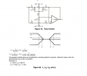
The LM4562 data sheet provides the attached schematic for the tone control. My big question right now is how to implement the tone control. Should it be placed before the volume control or after? I'd suspect before. Should I move the input dc blocking capacitors before the tone control, or leave them after? Will this affect the input impedance of the amp? I don't want the volume to change between having the tone on or off, or have any pop when switching.
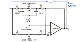
This is probably a total noob question too, but, for the tone bypass switch, can I do a simple bypass like I attached, or do I need to completely cut the tone section out of the signal path? Still learning...
While I'm here, I'll throw in a few questions about the power supply too that I've not found answers to yet.
1. What's the general agreement on the type of capacitor for the 100nF and 1.5nF? Poly Film? Tantalum? Disc?
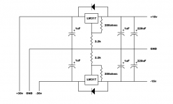
2. I've attached my initial plan for the additional regulated +-15v rail. I've pieced it together from datasheets and other schematics, so it may be totally wrong... Any suggestions? Is there a best place to pull from the 30v lines? Before/after the large filter capacitors?
3. Is a standard wirewound resister fine for the 1R 10w in the powersupply?
4. I'm thinking 24,700uF is overkill for my application. Right now I am considering using 2x 4700uF per rail. Do any other values need to change if I reduce the total capacitance?
I'd appreciate any suggestions, Thanks!
Other than the tone control, I'm planning a fairly "by the book" GC with a power supply based on the carlosfm design (but with less total capacitance) and an added regulated +-15v rail to use with the LM4562 tone control. I'll be feeding the amp from a Presonus firewire interface.
I know many may advise against a tone control, but where I'm going to be using this amp, I'd like to have the tone control. I plan to add a tone bypass switch for when it's not wanted/needed. I have some LM4562s and the tone control seems simple compared to other schematics I've seen, so that's why I'm considering it right now.
The LM4562 data sheet provides the attached schematic for the tone control. My big question right now is how to implement the tone control. Should it be placed before the volume control or after? I'd suspect before. Should I move the input dc blocking capacitors before the tone control, or leave them after? Will this affect the input impedance of the amp? I don't want the volume to change between having the tone on or off, or have any pop when switching.
This is probably a total noob question too, but, for the tone bypass switch, can I do a simple bypass like I attached, or do I need to completely cut the tone section out of the signal path? Still learning...
While I'm here, I'll throw in a few questions about the power supply too that I've not found answers to yet.
1. What's the general agreement on the type of capacitor for the 100nF and 1.5nF? Poly Film? Tantalum? Disc?
2. I've attached my initial plan for the additional regulated +-15v rail. I've pieced it together from datasheets and other schematics, so it may be totally wrong... Any suggestions? Is there a best place to pull from the 30v lines? Before/after the large filter capacitors?
3. Is a standard wirewound resister fine for the 1R 10w in the powersupply?
4. I'm thinking 24,700uF is overkill for my application. Right now I am considering using 2x 4700uF per rail. Do any other values need to change if I reduce the total capacitance?
I'd appreciate any suggestions, Thanks!
Attachments
For the tone control bypass you need to make sure that the op amp output is disconnected when the bypass switch is closed. Use a double take contact. The common pin is the output to the next stage Vo. NC is the output from the op amp after the feedback loop and NO the input Vi or vice versa.
- There is no general agreement. The best compromise in that place are ceramic caps, e.g. disc types. Second best choice are film types.
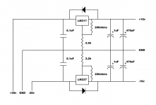
- For the negative rail you need to replace the LM317 with the LM337 and turn the flyback diode around.
Be aware that dropping 15 V will produce a lot of heat dissipation across the regulators. Even if your load are only two op amp channels you will need the TO220 version. If the load is higher, you should add heatsinks. Maybe you should consider to use 18 V types to reduce the voltage drop or add a series resistor on the 30 V side.
Attach the regulators after the big smoothing caps. - Yes.
- If you skip the four 10000 µF capacitors, skip the 1 R 10 W resistor. It forms a low-pass with the caps. Without the caps it will only waste energy.
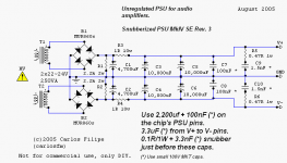
Hi all, in the suggested power supply circiut, what are R5+C9 and R6+C10 supposed to do? It looks like a snubber circuit put accross 24,700uF and already suitably bypassed by C7 and C8??
A more usefull place for a 1.5nF+0.47R etc might be across the AC input terminals of the bridge rectifier, but personally I put a 0.1-0.22uF capacitor accross each diode and leave it at that....
A more usefull place for a 1.5nF+0.47R etc might be across the AC input terminals of the bridge rectifier, but personally I put a 0.1-0.22uF capacitor accross each diode and leave it at that....
You have a few potential problems lurking... lets work backwards from the power amp.
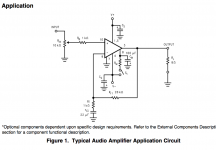
Picture 2. The LM3886 is fine. However it MUST HAVE a cap at the input to the volume control. Thats the top unconnected pin in the diagram. Why ? because any (even a few millivolts) of DC from the stages before will cause the pot to be crackly and noisy in operation. 10uf would be a suitable value. The value in conjunction with the volume control value determines the low frequency roll off point of the two.
Picture 4. The tone control bypass. You can't wire it like that because with it bypassed you are feeding the signal direct into the opamp output which will appear as a short to the signal. The switch has to take the signal from the either the tone stage or the source. So you need to take the signal from the wiper/contact of a DPDT type switch.
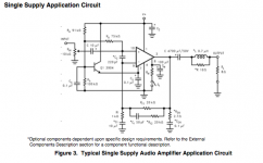
Picture 1. The standard application note and its fine except you also need a DC blocking cap on the input. I would suggest around 22uf. Why ? because the stage is open to any DC from the source components.
Picture 3. Is fine. (huge cap values aren't always the best approach, I'd be happy with a simple arrangement of just two caps around 3300 to 4700 uf). The amp rejects ripple and noise and the rails, the 1 ohms will actually cause the rails to be modulated at high current draw despite the large caps... swings and roundabouts.
If the amp has any hum and noise then its down to the layout and wiring/grounding rather than lack of smoothing.
Picture 5. Looks OK
The success or failure of any amp like this is pretty much 100% down to the physical implementation. Get that correct and it will be a winner")
Picture 2. The LM3886 is fine. However it MUST HAVE a cap at the input to the volume control. Thats the top unconnected pin in the diagram. Why ? because any (even a few millivolts) of DC from the stages before will cause the pot to be crackly and noisy in operation. 10uf would be a suitable value. The value in conjunction with the volume control value determines the low frequency roll off point of the two.
Picture 4. The tone control bypass. You can't wire it like that because with it bypassed you are feeding the signal direct into the opamp output which will appear as a short to the signal. The switch has to take the signal from the either the tone stage or the source. So you need to take the signal from the wiper/contact of a DPDT type switch.
Picture 1. The standard application note and its fine except you also need a DC blocking cap on the input. I would suggest around 22uf. Why ? because the stage is open to any DC from the source components.
Picture 3. Is fine. (huge cap values aren't always the best approach, I'd be happy with a simple arrangement of just two caps around 3300 to 4700 uf). The amp rejects ripple and noise and the rails, the 1 ohms will actually cause the rails to be modulated at high current draw despite the large caps... swings and roundabouts.
If the amp has any hum and noise then its down to the layout and wiring/grounding rather than lack of smoothing.
Picture 5. Looks OK
The success or failure of any amp like this is pretty much 100% down to the physical implementation. Get that correct and it will be a winner
:
:
Picture 1. The standard application note and its fine except you also need a DC blocking cap on the input. I would suggest around 22uf. Why ? because the stage is open to any DC from the source components.
The success or failure of any amp like this is pretty much 100% down to the physical implementation. Get that correct and it will be a winner[/QUOTE]
Hi I would also recommend a buffer before that tone control, as due to the treble components, the treble part has input impedance of less than 3K incertain position. An inverting x1 buffer with 10-47K resistors will help in this resect providing reasonably steady input impedance and low output impedance to drive the tone control components.
:
Picture 1. The standard application note and its fine except you also need a DC blocking cap on the input. I would suggest around 22uf. Why ? because the stage is open to any DC from the source components.
The success or failure of any amp like this is pretty much 100% down to the physical implementation. Get that correct and it will be a winner
[/QUOTE]Hi I would also recommend a buffer before that tone control, as due to the treble components, the treble part has input impedance of less than 3K incertain position. An inverting x1 buffer with 10-47K resistors will help in this resect providing reasonably steady input impedance and low output impedance to drive the tone control components.
Hi all, in the suggested power supply circiut, what are R5+C9 and R6+C10 supposed to do? It looks like a snubber circuit put accross 24,700uF and already suitably bypassed by C7 and C8??
A more usefull place for a 1.5nF+0.47R etc might be across the AC input terminals of the bridge rectifier, but personally I put a 0.1-0.22uF capacitor accross each diode and leave it at that....
So do I and probably most people with an engineering background.
The snubberised power supply by CarlosFM was hyped a lot in conjunction with the audiosector.com and chipamp.com kits. It is said to improve the sonic quality of those kits.
:
Hi I would also recommend a buffer before that tone control, as due to the treble components, the treble part has input impedance of less than 3K incertain position. An inverting x1 buffer with 10-47K resistors will help in this resect providing reasonably steady input impedance and low output impedance to drive the tone control components.
Thanks for the suggestion. I was just reading about buffered GCs and trying to determine if I needed that or not. I don't fully understand input/output impedance concepts yet.
Can you recommend a schematic for a buffer? I have lm4562s, opa2107s, and opa2132s on hand.
For the tone control bypass you need to make sure that the op amp output is disconnected when the bypass switch is closed. Use a double take contact. The common pin is the output to the next stage Vo. NC is the output from the op amp after the feedback loop and NO the input Vi or vice versa.
- There is no general agreement. The best compromise in that place are ceramic caps, e.g. disc types. Second best choice are film types.
- For the negative rail you need to replace the LM317 with the LM337 and turn the flyback diode around.
Be aware that dropping 15 V will produce a lot of heat dissipation across the regulators. Even if your load are only two op amp channels you will need the TO220 version. If the load is higher, you should add heatsinks. Maybe you should consider to use 18 V types to reduce the voltage drop or add a series resistor on the 30 V side.
Attach the regulators after the big smoothing caps.- Yes.
- If you skip the four 10000 µF capacitors, skip the 1 R 10 W resistor. It forms a low-pass with the caps. Without the caps it will only waste energy.
Thank you for the suggestions. I've revised my +-15v supply. I do have heatsinks for the LM317/LM337s to accommodate the voltage drop. I ran some tests and they should be adequate.
Maybe I'll get both ceramic and film caps and try them and see if I can determine any difference.
Attachments
You have a few potential problems lurking... lets work backwards from the power amp.
Picture 2. The LM3886 is fine. However it MUST HAVE a cap at the input to the volume control. Thats the top unconnected pin in the diagram. Why ? because any (even a few millivolts) of DC from the stages before will cause the pot to be crackly and noisy in operation. 10uf would be a suitable value. The value in conjunction with the volume control value determines the low frequency roll off point of the two.
Picture 4. The tone control bypass. You can't wire it like that because with it bypassed you are feeding the signal direct into the opamp output which will appear as a short to the signal. The switch has to take the signal from the either the tone stage or the source. So you need to take the signal from the wiper/contact of a DPDT type switch.
Picture 1. The standard application note and its fine except you also need a DC blocking cap on the input. I would suggest around 22uf. Why ? because the stage is open to any DC from the source components.
Picture 3. Is fine. (huge cap values aren't always the best approach, I'd be happy with a simple arrangement of just two caps around 3300 to 4700 uf). The amp rejects ripple and noise and the rails, the 1 ohms will actually cause the rails to be modulated at high current draw despite the large caps... swings and roundabouts.
If the amp has any hum and noise then its down to the layout and wiring/grounding rather than lack of smoothing.
Picture 5. Looks OK
The success or failure of any amp like this is pretty much 100% down to the physical implementation. Get that correct and it will be a winner
Thanks a lot for the suggestions.
I am planning on using input caps, but let me make sure I understand properly, put the input capacitors before the volume control (instead of after) because of the tone section's possible dc offset?
I didn't mean to say I was doing the minimum required parts. Just that I'm mostly working from the datasheet. I'm going to work through the datasheet's "GENERALIZED AUDIO POWER AMPLIFIER DESIGN" section and see what I come out with and then compare that with other schematics I've found around online. If anything, hopefully learn from the process. I'll post what I come up with.
On the basis of your circuit it has to go before the control. This is because the amp needs a DC path from pin 10to ground. Now there are better ways of doing this... remember all your circuits are just basic application notes and not refined designs.
Pin 10 ideally should connect to ground via a resistor that is the same value as Rf. That's the 20k in that diagram. Keeping these equal ensures that the amp "bias currents", that is to say the currents that flow out or the two input pins are equal and so generate an equal "offset" voltage. That helps keep the DC offset at the amp output as low as possible. Pin 10 should then be AC coupled to the wiper of the pot.
Pin 10 ideally should connect to ground via a resistor that is the same value as Rf. That's the 20k in that diagram. Keeping these equal ensures that the amp "bias currents", that is to say the currents that flow out or the two input pins are equal and so generate an equal "offset" voltage. That helps keep the DC offset at the amp output as low as possible. Pin 10 should then be AC coupled to the wiper of the pot.
So do I and probably most people with an engineering background.
The snubberised power supply by CarlosFM was hyped a lot in conjunction with the audiosector.com and chipamp.com kits. It is said to improve the sonic quality of those kits.
OK I get the deal!

Thanks for the suggestion. I was just reading about buffered GCs and trying to determine if I needed that or not. I don't fully understand input/output impedance concepts yet.
Can you recommend a schematic for a buffer? I have lm4562s, opa2107s, and opa2132s on hand.
Input impedance of an integrated amplifier is usually 10-47 K ohms; its so it doesn't unduly load equipment connected to it such as CD players etc.
See attached; it seems all the opamps you specify are unity gain stable so hould be ok, so it's up to you which to use or put a socket and choose afterwards! Make R1 = R2 in attached circuit the other resistor not really needed in audio (short "+ input" to 0V) but if you insist, when R1 = R2, R3= 0.5 x R1 (or R2!)
Suggested values R1 and R2 = 22K R3 if insisted apon, 10K is quite close enough.
Attachments
Last edited:
Also very important.
I'm pretty sure the LM3886 should have a zobel network (a cap and resistor in series) from the output to ground to ensure stability. Typically values around 0.1uf and 10 ohm.
I agree its to do with the non-complimentary output stages in power IC design and also mentioned in Mullard transistor circuits books. Especially important if the amp is to be connected to long speaker wires.
Also very important.
I'm pretty sure the LM3886 should have a zobel network (a cap and resistor in series) from the output to ground to ensure stability. Typically values around 0.1uf and 10 ohm.
I was planning on including the 0.7uH inductor and 10ohm resistor in parallel as shown in the suggested application. Is the resistor/cap to ground config better? Or is it a matter of which is easier? I do have 16aug magnet wire i was planning on using for the inductor.
Attachments
The resistor and cap to ground is a different thing altogether really. Many amps need those to ensure stability with no load (speakers) connected. Its a must have.
The output coil isn't always normally needed in practice. Its there to prevent small capacitive loads from causing instability... such as the long speaker wires blu_glo mentions. The 10 ohm across the coil damps any "ringing" caused when squarewave testing the amp. The coil isn't critical in value, just make sure its air spaced (not wound on a magnetic former) and of reasonably thick wire.
The latest diagram you have posted is a "single rail" configuration. Yes As long as you appreciate the differences there.
The output coil isn't always normally needed in practice. Its there to prevent small capacitive loads from causing instability... such as the long speaker wires blu_glo mentions. The 10 ohm across the coil damps any "ringing" caused when squarewave testing the amp. The coil isn't critical in value, just make sure its air spaced (not wound on a magnetic former) and of reasonably thick wire.
The latest diagram you have posted is a "single rail" configuration. Yes
As long as you appreciate the differences there.The resistor and cap to ground is a different thing altogether really. Many amps need those to ensure stability with no load (speakers) connected. Its a must have.
The output coil isn't always normally needed in practice. Its there to prevent small capacitive loads from causing instability... such as the long speaker wires blu_glo mentions. The 10 ohm across the coil damps any "ringing" caused when squarewave testing the amp. The coil isn't critical in value, just make sure its air spaced (not wound on a magnetic former) and of reasonably thick wire.
The latest diagram you have posted is a "single rail" configuration. Yes
Indeed.
- I do tend to still include the coil as it also stops demodulation of strong AM radio channels (yes they still exist) in the output devices. You'd have thought the Zobel network might have prevented this in theory.......
AM signals could be an issue in some locations so yes, the coil will help. The impedance of the zobel network isn't low enough to "short" any AC hash that come in via the speaker leads. If you connect a good and sensitive scope across an open circuit speaker and its cable its surprising what you see. A 10 ohm shunt does nothing to dampen it.
.............. I do tend to still include the coil as it also stops demodulation of strong AM radio channels .................... You'd have thought the Zobel network might have prevented this in theory.......
Use Dr Cherry tapping point for the NFB back to the -IN input.AM signals ................ so yes, the coil will help. The impedance of the zobel network isn't low enough to "short" any AC hash that come in via the speaker leads......................
That adds an extra pole of attenuation for RF injected into the speaker terminal.
Use Dr Cherry tapping point for the NFB back to the -IN input.
That adds an extra pole of attenuation for RF injected into the speaker terminal.
'gis a clue .... who/whats Dr. Cherry???
- Status
- This old topic is closed. If you want to reopen this topic, contact a moderator using the "Report Post" button.
- Home
- Amplifiers
- Chip Amps
- LM3886 GC with LM4562 tone control