I have followed and built the Tube Buffer circuit based on the JLTi DIY version.
Initially I misunderstood the PSU for the Tube buffer and connected
a single pair of +/-35v to both channel of the 6922's Pin, which when
powered up, created loud noise/buzzes like a mis-tuned AM radio.
After rectifying the problem, I built another +/- 35V and that solved
the buzzes, no more hum.
Now the problem is, even after validating that I'm getting the correct
voltages on all pins, I only get the faintest amount of music coming
thru my test speakers. I'm using a single tx with 24-0-24 v for the
tube, a single 12v tx rectified with 7808 with 7.1ohm resistor in series
to the filament.
What could be wrong ???
PS: The amplifier section was built weeks earlier based on the non-tube
version of JLTi and it was making music, so I kinda rule out problems
relating to the amp section.
will.
Hi Will,
For starters can you tell us if you are using the circuits shown on my VBIGC page ?
I don't use the resistor after the 7808 although I can't see that it would make much difference.
Don't worry, I am sure that we can solve your problem and when we do, it will have been worth the trouble!
For starters can you tell us if you are using the circuits shown on my VBIGC page ?
I don't use the resistor after the 7808 although I can't see that it would make much difference.
Don't worry, I am sure that we can solve your problem and when we do, it will have been worth the trouble!
> validating that I'm getting the correct voltages on all pins
List pin-numbers and exact voltages. Yes it is tedious to type all that, but you need someone else's eyes to look at your work and see if there is an error. Could be as simple as mixed up pin numbers.
Does the tube light up with an orange glow in its center?
And remember it will take 10 or 20 seconds for the tube to warm-up and start working. Apologies if you knew that, but I've met a few people too young to remember tube warm-up.
Hi Nuuk and PRR,
Thanks for you replys. Yep I did follow the circuits based on your website. Infact I have read your advises several times and indeed made just that. The filament and tube PSU are connected directly to the mains just like the JLTi hence the adequate warm up time.
OK to cut things short, PROBLEM IS SOLVED !!!
Of all things that I have checked e.g. voltages, soldier connections, reading the forum from front to back and back to front and even taking the trouble to change both the LM3875 pins, IT WAS MY DARN TEST SPEAKERS !!! I must have damaged them during my first startup which ended up in huge buzzes..... duh...
Right, coming back to the amp, here's what I've noticed from the non-buffered to the bufffered version :
1) Better overall air and more refined highs
2) Switch on thump
3) Louder humm...
I was thinking of regulating the +/-35 volts for the tube, is it possible to use a 28v dual secondary tx pumping thru only LM317s (I have a whole bunch of them) on the +ve and -ve rails to get 35v ?
will.
That's better Will, at least you have something coming out of the speakers now!
As regards your findings, I agree with number 1.
As you probably know, I use speaker protection which doesn't connect the speakers until well after I have powered up so I don't get a switch on thump.
I do get slightly more hum than with the 'basic' IGC. My findings having tried several different configurations of IGC is that the quietest version (least hum/no switch onthump) is with a wire from non-inverted input to ground. With Joe's circuit we have the 1 meg resistor to ground and I have found that although this arrangement decreases DC offset, it does increase hum and switch on noise!
So how bad is your hum. Mine is only audible close to the speakers which are very efficient full-range units in open baffles which is going to ruthlessly expose any such noise anyway!
I can live with the switch on thump, but not the hum; thanks for tip, will try bypassing the 1meg. The hum is pretty audible about 1 feet away from the speaker. Yeah perhaps I ought to pay more attention to my grounding.
Today I tried a voltage regulator for the tube with a LM317/337 regulator to get +/- 35 v (using a single 30-0-30v Tx). Am pretty disappointed with the results , not sonically, but the noise I get that is worser than hum, sounds more like digital buzzes. I'm using 1000uf on the front and 470uf on the final, with 1uf film caps for bypass, which I think should be adequate enough for a silent operation. Have you any experience with those ?
will.
Just an update, I have removed the voltage regulators, replaced the Tx with 30-0-30v, and a 2K2 resistor (instead of 220R) between a 1000uf and 470uf cap. Overall, am getting a voltage of around 36.8v on the tube, and the amp is buzz free. Hmmm, speaking about wrong regulator application.
"That's good news Will! Do you have any pictures of your amp yet?"
- Will post some in a couple of days time when my camera arrives...
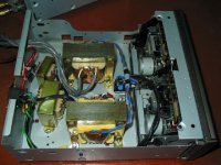
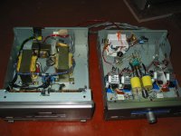
Just to give you an idea, I'm using 2 separate chasis for Tx and amplifier - both chasis salvaged from a Yamaha Tape Deck and a Yamaha CDP (at least they have the same aspec ratio).
4 Tx in the first chasis - Lt, Rt, Tube, Filament.
Amplifier chasis consist of the following - Step Attenuator (wafer anf attenuator from RS, resistors using matched carbon 5% i.e. normal stuff), Voltage regulator LM338 x 4 including heatsinks, Tube 6922 Electro Harminix, Supply and Filament Regulator. Pretty packed too.
- Will post some in a couple of days time when my camera arrives...
Just to give you an idea, I'm using 2 separate chasis for Tx and amplifier - both chasis salvaged from a Yamaha Tape Deck and a Yamaha CDP (at least they have the same aspec ratio).
4 Tx in the first chasis - Lt, Rt, Tube, Filament.
Amplifier chasis consist of the following - Step Attenuator (wafer anf attenuator from RS, resistors using matched carbon 5% i.e. normal stuff), Voltage regulator LM338 x 4 including heatsinks, Tube 6922 Electro Harminix, Supply and Filament Regulator. Pretty packed too.
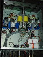
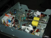
Some more pics of the guts: Last but not least, the 11 step attenuator (make bf break) having total of 24.1K ohms from RS. This made a huge difference in improving sound stage width and depth compated with an Alps Blue. The resistors are plain carbon 5% but carefully matched. Who says carbons do not sound good ???")
Attachments
Who says carbons do not sound good ???
Certainly not me Will! I like to mix and match resistors anyway so that one type does not dominate the sound.
A good example of using existing cases for a project. As the case can be the most expensive item in a chip amp, it makes good sense! Would you like to be included in the
DD Gainclone Gallery ?
I like the ruff and ready look of your amp and layout Will (that's a compliment btw! ).
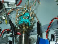
It looks like you are using just the single valve for both channels - was there a reason for this? Did you remove the V regulators completely?
- Thanks. This is the first time I'm building this kind of amp so to save on cost and also to maintain simplicity, I'd use the single valve. Pin 9 is connected to the chasis BTW to minimise x-talk. Yeah the V regulators are gone cos' they are really noisy.
Certainly not me Will! I like to mix and match resistors anyway so that one type does not dominate the sound.
- Do you roughly have a formulae, like front end to use metal film, feedback resistors Riken etc ?
Would you like to be included in the
DD Gainclone Gallery ?
- With pleasure.
Do you roughly have a formulae, like front end to use metal film, feedback resistors Riken etc ?
Not really. I like to use Welwyn RC55's where I need accuracy. Other than that I 'sprinkle' a few of each kind here and there.
Seems to work.- Status
- This old topic is closed. If you want to reopen this topic, contact a moderator using the "Report Post" button.
- Home
- Amplifiers
- Chip Amps
- Tube Buffer IGC - need help ....