I would have thought an op-amp oscillator is easiest to get working, but if you insist, Rod Eliott has offered a four transistor AF oscillator design
Audio Test Oscillator
which looks very good (as are all his articles). A circuit can be done with only two transistors but the ones I've come across using google briefly appear to have some fundamental flaws. This is what happens when people rely on computer simulations too much and not the good old "solder-and-and-try-it-out" method!!
Attachments
I think you'll save yourself a lot of aggravation spending cash on a pair of unassembled printed circuit boards.
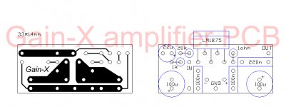
As I already said, LM1875 is directly interchangeable with TDA2030, 40, 50 types. I seen PCBs for around €10 or so!
You can then tweak components knowing the wiring's already done right for you!
TDA2030A Amplifier Amp board Components DIY kit BTL/OCL | eBay
As I already said, LM1875 is directly interchangeable with TDA2030, 40, 50 types. I seen PCBs for around €10 or so!
You can then tweak components knowing the wiring's already done right for you!
TDA2030A Amplifier Amp board Components DIY kit BTL/OCL | eBay
An
STK412-170 would seem awesome,anyone can please post an schematic with layout and most importantly,are they good?!
That will need a serious heatsink to realise it's potential!
I knowThat will need a serious heatsink to realise it's potential!
Using this schematic the speker goes up and there is a faint trumpet noise,while nothing is hooked up to the input ,may this be becaue i used 55k instead of 50k
55K instead of 50K is not a problem just changes gain slightly.
- what value is R3?
100k55K instead of 50K is not a problem just changes gain slightly.
- what value is R3?
For least DC offset on the output R3 should be the same value as the feedback resistor in your case 55K. The datasheet suggests a 22K resistor in this position on P.2 for the dual supply application. So 100K may be a bit high.
http://www.ti.com/lit/ds/symlink/lm1875.pdf
http://www.ti.com/lit/ds/symlink/lm1875.pdf
Last edited:
Ok i thought it for something else but i will ad another 33k+22k resistorFor least DC offset on the output R3 should be the same value as the feedback resistor in your case 55K. The datasheet suggests a 22K resistor in this position on P.2 for the dual supply application. So 100K may be a bit high.
http://www.ti.com/lit/ds/symlink/lm1875.pdf
Sure!Can you show me a pic of your power supply and wires? - The actual project as you have it on your bench, not the schematic!
As for psu just an computer psu with 12 0 -12v outs usen on amp
Attachments
![DSCF2882[1].jpg](/community/data/attachments/300/300712-c43ffb1fe54ac56ab8b2b4cf998c26da.jpg)
Is it too difficult to find a 15+15V ( 30 V center tapped)50/60 W transformer ?
You said that you have a 18+18 V one...is it a too high voltage for the application?
When I told you not to mix Pc & audio things , there are some reasons why:
a clean linear supply....is a clean linear supply !!
When you have it done, you know that if something's not going to work, it's not
its fault.
Second, what is written on the decal on the PC psu ? + 12V @ how many amperes max ?
and what about the -12 V line ? is it the same ? I guess no
and EKKKK! what and where are those ceramic caps ?
Its too high voltage for testing and could damage something,but once the amp is out of beta testing i will use it,the psu is 50a 12v and just 0.8a for the minus voltage so that might be a problemIs it too difficult to find a 15+15V ( 30 V center tapped)50/60 W transformer ?
You said that you have a 18+18 V one...is it a too high voltage for the application?
When I told you not to mix Pc & audio things , there are some reasons why:
a clean linear supply....is a clean linear supply !!
When you have it done, you know that if something's not going to work, it's not
its fault.
Second, what is written on the decal on the PC psu ? + 12V @ how many amperes max ?
and what about the -12 V line ? is it the same ? I guess no
and EKKKK! what and where are those ceramic caps ?
And yes it didicult to find one,i thried so hard for 3 years to find one for a tda7294 and they were very expesive,util recently my mom accidentaly therw out the tda7294
Last edited:
Its too high voltage for testing and could damage something,but once the amp is out of beta testing i will use it,the psu is 50a 12v and just 0.8a for the minus voltage so that might be a problem
And yes it didicult to find one,i thried so hard for 3 years to find one for a tda7294 and they were very expesive,util recently my mom accidentaly therw out the tda7294
The max transformer voltage I'd recommend is 22-0-22Vac too much more and you'll risk going over the max. You'll need a bridge rectifier rated 5A 200PIV and a couple of off-board electrolytics at least 4700uF and at 35V or more. You should also tidy up the wiring on that board. You should also have a couple of 100uF (gain 35V) on the board wired in close to the IC pins, which, I assume, is also where your ceramic disk ones are. The ceramics are fine for supply rail decoupling so no problems there. You should follow the datasheet I posted earlier as I notice other components missing.
And your power supply is OK for testing but not so to use in anger!
Thanks to you it now works ,im so happy i will write your name on the pcb so everybody who takes a peek in the casing will see your name and ask why is something written on the pcb,i will say to threm that you helped me the mostThe max transformer voltage I'd recommend is 22-0-22Vac too much more and you'll risk going over the max. You'll need a bridge rectifier rated 5A 200PIV and a couple of off-board electrolytics at least 4700uF and at 35V or more. You should also tidy up the wiring on that board. You should also have a couple of 100uF (gain 35V) on the board wired in close to the IC pins, which, I assume, is also where your ceramic disk ones are. The ceramics are fine for supply rail decoupling so no problems there. You should follow the datasheet I posted earlier as I notice other components missing.
And your power supply is OK for testing but not so to use in anger!
- Status
- This old topic is closed. If you want to reopen this topic, contact a moderator using the "Report Post" button.
- Home
- Amplifiers
- Chip Amps
- lm1875 fizzing away probelm