is it possible to get 1 watt rms or even 5 watts rms?from a 5 watt chip amp?
how much capacitance should I need for the output? 2200uF? 10,000uF? I want the amp to nail the low frequencies down to 0.5hz as best as it can without distorting..
Is it possible? this is the chip i used
LA4225 datasheet(2/3 Pages) SANYO | Monolithic Linear IC Audio Output for TV application 5W Monaural Power Amplifier
and i have a 4.7uF capacitor for the input instead of 2.2uF's
and at the moment I have 6,200uF's for the output instead of 470uF's
It already nails the lows really nicely and sounds clean. very minimal static too.
if I put 10,000uF's how good would the low frequencies get then?
At first I only had 2,000uF's but adding the extra 4,200uF's added a lot more to it already..
Would there really be any use for having a 10,000uF cap in place for this chip?
Or is that just overkill?
Last edited:
What are you using this for?
Why do you need output at .5hz?
Is this being used as a reference of some sort, hence your requirement for a specific power?
Output cap is for blocking DC on speaker. 6,200uf is overkill.
Save your 10,000uf cap for the PSU or another project.
Why do you need output at .5hz?
Is this being used as a reference of some sort, hence your requirement for a specific power?
Output cap is for blocking DC on speaker. 6,200uf is overkill.
Save your 10,000uf cap for the PSU or another project.
Last edited:
I want to hit good bass notes and have overall super good clear sound quality for my speakers so they will hit with the best clearest sounding bass and hit the lowest frequency that they can..
The song bass I love you plays notes a little lower than 1hz and my amplifier can hit them all even though it cost absolutely nothing to put together this little chip amp since i salvaged the parts from an old TV motherboard that i found lying in a pile of scraps on the side of the road.
and the speakers actually show cone movement at less than 1hz easily
And the overal sound quality is amazing compared to something that costs probably 50 dollars. And If I had really good nice set of speakers it would sound amazing..
Right now I have the chip with heatsink all mounted nicely in a cardboard box.. With the power supply hidden in the box as well..And I have speaker terminals so I can easily attach or unattach almost any kind of speakers... Also with a headphone jack plug that I can just simply plug right into my computers headphone output... the sound quality is really good too even for a mono setup..
I want to make another clone of this amplifier so I can have a stereo amplifier.. one for the left channel. and one for the right channel..
And if possible I could brigde the amplifiers somehow.. but that's another thing..
")
it wouldn't have as much power would it though right? and wouldn't that introduce ultrasonic pulses into the audio signal instead of normally just using a capacitor to block DC?
Oh yikes I just tried putting 19 volts to the amplifier chip for a few seconds
And Omg the 10 watt speaker bottomed out from a 5 watt IC chip amplifier
And there was no amplifier distortion.... only the bottoming out of the 10 watt speaker
Yikes I just got over 10 watts out of a 5 watt amplifier chip O.O that's a little scary..
But I hooked it back up to the 12 volt power supply instead so I think the chip is okay... It didn't get warm when I unplugged the power cord and checked the chip..
Maybe the massive heatsink helped save the chip?
Last edited:
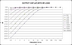
You can easily figure out how much each frequency will be affected by each cap.
A capacitor in series with the signal, with a resistance to ground downstream from that, makes a passive RC high-pass filter.
If you know how a two-resistor voltage divider works, you can think of the capacitor and resistor as a frequency-dependent voltage divider. At lower frequencies, the apparent resistance of the cap is higher and a larger proportion of the available voltage is dropped across the cap, and less across the resistor. If the RC are at the input end, the voltage across the resistor to ground is what your amp's input sees. If at the output, the voltage across the speaker's "resistance" to ground is what you hear. Either way, it's lower at lower frequencies. How MUCH lower depends on the capacitance (and the resistance to ground).
A common resistive voltage divider, with series resistance Rs followed by a resistance to ground R, has
Vout = Vin x (R / (R + Rs))
i.e. The proportion that the R to ground is, of the total resistance, is the proportion of the input that gets to the output.
It's almost the same, for a series capacitor and a resistance to ground, but we need to know that the apparent resistance of a capacitance, to AC at some frequency, f, is 1/(2πfC).
So then the voltage-divider equation becomes:
Vout = Vin x (R / (R + (1/(2πfC))))
You could plug in values and use the equation in that form, or, we can re-arrange it to get:
Vout/Vin = 2πfRC / (2πfRC + 1)
Just remember to divide microfarads by 1000000, to get Farads to use in the equation. And use f in Hz and R in Ohms. π is about 3.14.
We could make the equation more useful, for your case, if we solved it for C, so you could pick a frequency and a Vout/Vin ratio and just calculate the needed capacitance.
I think this is right:
C = (Vout/Vin) / (2πfR x (1 - (Vout/Vin)))
If you wanted it solved for R, instead of C, you should be able to just SWAP the R and C, in that equation.
NOTE that if you make your input resistor larger, less capacitance will give you the same response. i.e. Increasing the resistance to ground gives exactly the same effect on the frequency response as increasing the capacitance.
But you shouldn't raise the input resistor's value TOO awfully high, because higher-value resistors generate more noise, and also pick up interference more easily, from the environment. (On the other hand, they're also easier for the source to drive.) A value of 10K to 20K or so should be fine, and maybe higher. I'd probably just try some much larger values and see if it has too much noise or not. Doubling the resistance is just like doubling the capacitance, as far as the frequency response is concerned. (And using 10x the resistance would give the same frequency response as using 10x the capacitance.)
If calculating with the R for a speaker, you can use 8 Ohms or 4 Ohms or whatever the rating is. But be aware that the speaker's actual impedance can change as the frequency changes.
Most people look at what's called "the minus 3 dB frequency", or "cutoff frequency", when talking about filters. That's just the frequency where the output is down to 3 dB less than the input. For voltages, that's a factor of 1/sqrt(2), or 0.7071, i.e. 70.71% of the input voltage makes it to the output. For power in Watts, -3 dB would be a decrease of 50%.
The -3dB frequency for a high-pass (or low-pass) passive RC filter is:
f(-3dB) = 1 / (2πRC)
Usually, for a high-pass filter, you'd want to make that frequency be at most 1/10th to 1/100th of the lowest frequency that you wanted to keep.
Last edited:
Hi,
No music or sound format has notes below 1Hz, period.
The lowest notes will be in the 0.1 channel of multi-channel
and hardly any of them will have any notes below about 16Hz.
You may think the modulation of cone excursion is a frequency,
the cone "appears" to move in and out at low frequency, but
that isn't producing low frequencies, its an optical illusion.
rgds, sreten.
I can physically see the speaker moving at 1hz if I play a 1hz tone in audacity... 1hz is seriously slow.. i can clearly tell the difference between 1hz and 30hz
you can hear 30hz
but you cant hear 1hz its utterly impossible.. unless the entire earth shakes in an apocalpyse earthquake..
you can hear 30hz
but you cant hear 1hz its utterly impossible.. unless the entire earth shakes in an apocalpyse earthquake..
Hi,
So response down to 0.5Hz is pointless. As is down to DC, all drivers
do DC by moving off centre depending on the voltage, but it does
not matter, visually you can see it, practically its useless.
Audacity may do 1Hz but :
"The song bass I love you plays notes a little lower than 1hz"
doesn't, whatever you are actually referring to.
rgds, sreten.
is it possible to get 1 watt rms or even 5 watts rms?from a 5 watt chip amp?
First of all, I believe there is technically no such thing as "Watts RMS", or "RMS power", that's just confused marketing speak. Output power in Watts is computed using RMS voltage/current.
Secondly, you can certainly get 1 Watt out of a 5 Watt chip amp. A chip amp being rated at 5 Watts just means 5 Watts is the maximum it can put out before being damaged by overheating. The chip isnt always putting out 5 Watts no matter what. If you turn your music down quiet enough the chip will happily put out 0.1 Watts. The same is true of a 500 Watt amp or any other amp.
Earlier DUG suggested you get rid of the output capacitor and go direct coupled, to avoid filtering out the super low frequencies that you for some reason care about, and you said "it wouldn't have as much power would it though right". I don't believe that is true at all. The output capacitor does nothing to provide power, you won't get more power out of an amp by increasing the output cap and keeping the input levels and gain constant. The output cap just blocks DC, and filters low frequencies as a side-effect. In a design that doesn't need a DC blocking cap (like one with a dual power supply, or a virtual earth), there will be no filtering of low frequencies with no influence on the output power.
I am pretty sure putting 1 Hz through a loudspeaker is a Very Bad Idea, and will eventually kill a speaker for the same reasons that DC will.
you haven't seen it for yourself.. I have..
Hi,
Your tedious lack of basic understanding is frustrating. I've seen
a shedload more of everything than you have, comes with age.
Except now I understand most of it, not misunderstand it.
rgds, sreten.
Last edited:
the cone "appears" to move in and out at low frequency, but
that isn't producing low frequencies, its an optical illusion.
Is this kind of like the illusion where the wheel of a car looks to be rotating slowly backward, even though it is rotating rapidly forward, because of the eye's low "sample rate"? The cone is moving at some audible frequency with the property that when the eye takes snapshots at around 24 Hz it appears to be smoothly moving at some lower frequency? Kind of like a visual equivalent of aliasing, actually, I guess.
Also, sreten, how are you able to be absolutely certain that the song this guy is on about does not contain sub-1 Hz content? I don't doubt you on that point for a second, but I'm interested in learning: is there something about the decoding algorithms for mp3 and similar formats which makes this technically impossible? Does the Redbook standard or something like it prohibit frequencies below a threshold? Or is it just the case that any and all professional recording studios would unquestionably filter this kind of sound out to protect equipment?
try the song on your own speakers..
If you see your speaker cone moving around 20hz 10hz or less. you got a good subwoofer and amplifier..
And the song actually does play that low.. If you open the file in audacity and look through the waveform its pretty obvious..
If I removed the capacitor I would have 6-12volts DC going to the little tiny 10 watt speaker :O
Last edited:
Also, sreten, how are you able to be absolutely certain that the song this guy is on about does not contain sub-1 Hz content? I don't doubt you on that point for a second, but I'm interested in learning: is there something about the decoding algorithms for mp3 and similar formats which makes this technically impossible? Does the Redbook standard or something like it prohibit frequencies below a threshold? Or is it just the case that any and all professional recording studios would unquestionably filter this kind of sound out to protect equipment?
Hi,
Your last point applies to nearly everything. There is nothing in the
standards to prevent silly levels of very low frequencies down to DC.
rgds, sreten.
try the song on your own speakers..
If you see your speaker cone moving around 20hz 10hz or less. you got a good subwoofer and amplifier..
And the song actually does play that low.. If you open the file in audacity and look through the waveform its pretty obvious..
If I removed the capacitor I would have 6-12volts DC going to the little tiny 10 watt speaker :O
Hi,
Making out your right and providing no information whatsoever so
that people cannot check it is a pretty pointless exercise in ego.
You need to rearrange your attitude to knowledge and information.
rgds, sreten.
Last edited:
If I removed the capacitor I would have 6-12volts DC going to the little tiny 10 watt speaker :O
With a single-supply amplifier, unbridged, sure. By using a bridged amplifier, or a dual-supply amplifier (either with a true dual-supply or a single supply using a virtual earth, although that last option has other problems), you can connect your amp directly to your speakers with no capacitor and there will be no (or very little) DC through them. Then you can use Audacity or whatever to play arbitrarily low frequencies (and risk damaging your speakers). If you really are fixated on < 1Hz content for some reason, this is probably the way to go, otherwise you will need stupidly large (and expensive) capacitors.
- Status
- This old topic is closed. If you want to reopen this topic, contact a moderator using the "Report Post" button.
- Home
- Amplifiers
- Chip Amps
- creating 1 watt rms power from 5 watt chip amp?