Hi everyone,
I'm testing on a breadboard a TDA7297 based design, very similiar to the one found on the datasheet, the only problems is that I can't use two distinct ground paths, one for power ground, and the other one for the signal ground, where is connected the input ground signal and the signal path of an headphones amplifier, the problem is when I mount the amplifier in this configuration it begins oscillating. It only works with power and signal ground tied together, I've also tried to connect directly the input ground to the supply capacitors but without any success. The headphones amplifier don't have a good behaviour when is signal ground is directly connected to the power supply ground without any connection to input ground. If I connected the signal ground of the headphones amplifier to the signal ground of the TDA7297 I have signal injection in both amplifiers, with TDA7375V this doesn't happens because the two ground are distinct but I got problems due to instabilities.
If I use the STA540 I can solve this two problems?
I've also told to build this amplifier on pcb layout but I don't no anything about pcb layout, and I'm afraid that I can't complete this project.
Thank you very much for your atention,
Best regards,
Daniel Almeida
Last edited:
Pictures of the circuit
Hi everyone,
As suggested by Mooly I'm posting some pictures of the amplifier and other components that I've mounted.
Thank you very much for your atention,
Best regards,
Daniel Almeida
Hi everyone,
As suggested by Mooly I'm posting some pictures of the amplifier and other components that I've mounted.
Thank you very much for your atention,
Best regards,
Daniel Almeida
Attachments
-
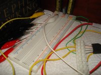
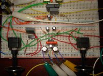 Headphone amplifier (TDA2822M) and input potentiometers (left - TDA7297, right - TDA2822M).jpg647.6 KB · Views: 259
 -
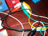 Improvised input connection.jpg514.7 KB · Views: 249
 -
 Power supply (capacitors and bridge rectifier).jpg447 KB · Views: 243
 -
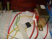 Power supply(transformer, rectifier and bridge rectifier).jpg520.4 KB · Views: 241
 -
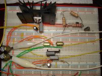 TDA7297 (power amp) and LM338T (linear voltage regulator).jpg653.9 KB · Views: 241
 -
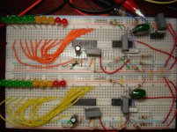 Two channel vumeter.jpg598.3 KB · Views: 83
Hmmm...
The problem is that while it looks logical visually as a layout, in practice there are many many interactions. The breadboard conductors are anything but zero resistance and impedance and herin lies the problem. The "grounds" are able to interact with each other causing instability.
There's no easy answer other than to say that laid out correctly on a PCB the problems will disappear. That said it can be done on a breadboard but its not pretty. You would have to take wire spurs and solder the appropriate grounds together so that they don't run along the breadboard where other components are tagged in to the chain.
Its something that can't be underestimated. You might think that a cm or so of breadboard conductor must be "almost short circuit". It isn't.
So do you think it's better to put all this things together on a pcb layout, using star ground topology, but I'm afraid that this problems could occur also at pcb.
In the PCB layout where I connect input ground, knowing that I have two amplifiers for the same input signal?
Thank you very much for your help,
Best Regards,
Daniel Almeida
In the PCB layout where I connect input ground, knowing that I have two amplifiers for the same input signal?
Thank you very much for your help,
Best Regards,
Daniel Almeida
- Status
- This old topic is closed. If you want to reopen this topic, contact a moderator using the "Report Post" button.