Of course, but this thread is about more current, not more voltage.
But twice voltage through same resistance gives twice the current.
DC Offset Resistors.
Ok, from what I understand, the problem with the DC offset can be corrected matching the feedback resistors, and that means using the same high precision resistors in all locations.
I have few Mouser part numbers for those resistors, can you please check them and tell me if these are OK to use:
200K 0.5% 400V Mfr. #: HV732ATTD2003D
47K 0.1% Mfr. #: ERA-6YEB473V
10K 0.1% Mfr. #: PNM0805E1002BST5
5.1K 0.1% Mfr. #: W0805R035101B-R1
Again, this can be found at www.mouser.com .
These boards have the same issue as the XY boards, the input signal ground and main ground need to be separated. Can you guys tell me where the cuts need to be made in the PCB to separate these grounds?.
I have more questions, but I'll post more later.
Thank you.
But twice voltage through same resistance gives twice the current.
Of course, but are we going to get twice the voltage swing into even 8 ohms with a simple bridge amp? No we are not. A look at the data sheet claims
- 68 watts into 4 ohms with +/- 28V
- 38 watts into 8 ohms with +/- 28V
- 50 watts into 8 ohms with +/- 35V
What does that mean for our bridge amp? That we can get 136 watts into 8 ohms with +/- 28V. Forget +/- 35V with a bridge amp. Forget about 4 ohms.
Now if we parallel 2 chips in each leg of the bridge (total of 4 chips/channel), we can up the supply to +/- 35V and get 200 watts into 8 ohms. We can run it off of +/- 28V and get around 250 watts into 4 ohms.
I home my math is correct
 but more importantly I hope you're getting the picture of what I'm talking about.
Running these chips parallel into a lighter load can theoretically avoid tripping the protective circuitry. It should result in a lower distortion amplifier capable of handling cranky loads better. Theoretically, of course.
")
Hello,
Each LM 3886 chip will be different in the way that the offset voltages will never be the same, even if you use the same feedback resistors with 0,00000000001 % tolerance. So you have to tune out the offset voltage of each chip manually by a adjustable resistor. After tuning and several warming ups, you replace the adjustable resistor by a fixed one.
See my thread: "LM3886 without electrolytic feedback capacitor and (hardly) no DC offset voltage", how to do this. With a feedback capacitor it's even easier.
Marc.
Agreed - I suspected the link I posted hadn't cleared up that question. Those adjustments are interactive and each effects the other two. I did a lot of insertions and removals as I didn't have adjustables. With the components I used ~ 11 mv (vendor docs suggests 5 mv as good) was the best 3-way match I could get. It's a bit of a pain but well worth the effort.
Marc Vi., where is your thread about the DC Offset?. Can you please post a link to it. I am getting some adjustable resistors as required by the PCB's, I already have a part number selected from Mouser, I don't have it handy right now but I'll post it soon so you guys can tell me if these are right.
Thanks.
Thanks.
I also want to know about these additional boards I've seen being used by other builders using the 3 chip parallel, I found two at the auction site, which one is better, and do I really need to use this or I can build my amp without it?.
Unbalanced]Unbalanced to Balanced Stereo Preamplifier for BTL | eBay to Balanced Stereo Preamplifier for BTL | eBay[/url]
BTL]BTL Bridge Board XLR to Balanced Board DIY Kit | eBay Bridge Board XLR to Balanced Board DIY Kit | eBay[/url]
Thanks again.
Unbalanced]Unbalanced to Balanced Stereo Preamplifier for BTL | eBay to Balanced Stereo Preamplifier for BTL | eBay[/url]
BTL]BTL Bridge Board XLR to Balanced Board DIY Kit | eBay Bridge Board XLR to Balanced Board DIY Kit | eBay[/url]
Thanks again.
This is the thread:
http://www.diyaudio.com/forums/chip...y-no-dc-offset-voltage.html?highlight=Marc+Vi.
You have to change the placing of the components on the board a little bit.
http://www.diyaudio.com/forums/chip...y-no-dc-offset-voltage.html?highlight=Marc+Vi.
You have to change the placing of the components on the board a little bit.
Hello,
I know this schematics. I don't know if you also get - with the board - building instructions and instructions how to tune the offset voltages by the three adjustable resistors of 50 K. If so, please send it to me. If not, I think I can help you.
I have build myself a single non-inverting LM3886 amp. And I did measurements on that amplifier. With this experience and my experience of amplifiers in general, I gave some proposals for improvements. Let me hear if you are interested.
Marc.
Thank you, Marc.
Hi Marc:
No, the seller did not provide any building instructions, only the schematic posted and a bill of materials.
Yesterday I ordered all the stuff I need to start working on these PCB's except the terminal connectors, I'm still looking for those.
I have no clue on how to adjust the DC Offset with the three variable 50K resistors, so yes, I need your help in that department, and also with everything else. I need to know what toroidal I will need for this, I believe I have a 28V and 24V at home, also what kind of power supply, and if I will need that balancing PCB.
I also built a single non-inverted LM3886 amplifier with the help of many people here, specially AndrewT and Pacificblue, but I see this parallel amp is a totally different thing. I love the sound from the single one I built, that's what motivated me to build this.
Some of the parts I ordered from Mouser are back ordered and I requested to ship them all together so it will take a while until I get them.
And yes, again, I'm new to all this, I need ALL the help I can get, thank you very much.
Here is the note I received back a year or so ago from Stanton at Jim's Audio on eBay:
"The DC offset voltage can be measured by using voltmeter, one probe to the output point, and another probe to the ground. The signal ground and the power ground are the same. If there is a voltage, then adjust the trimmer to reduce the voltage. If the output DC is so low ( say below 5mv) then there is no need to adjust. For 'one by one' it really means connect the 0.22 ohm resistors one by one to ensure each LM3886 has the minimum offset before hook all three together."
Output point meaning pin 3 on the LM3886 if that's what you choose to use. With the single resistor installed you can catch it at the output pad on the board.
It's the method I used and hopefully will be helpful to some.
Last edited:
Oké,
If you have the board and all the components, you assembly the board except for the resistors of 0,2 ohm: R7, R9 and R10. You do not place them.
You make a bridging wire over R7 but not the others. There is no input signal. You measure the offset voltage of the first amplifier and you tune the offset voltage to 0,0 mV by R4. Then you connect a speaker and put a signal (for instance music) on the input. You boost the input signal so the amplifier will be warm (but not too hot) for let's say ten minutes. You then shut down the input signal, wait a little while, measure the offset voltage and tune it to 0,0 mV by adjusting R4. You repeat this procedure several times.
You remove the bridging wire over R7 and make a bridging wire over R9. Then you repeat the same procedure for the second LM3886.
At last you do this for the third LM3886.
After doing this for the three amplifiers individually, you do a final measurement at each output to be sure that the offset voltages will still be around zero mV. Then you place the resistors of 0,2 ohm: R7, R9 and R10.
Now the amplifier is ready for playing music. If you have a working amplifier, I maybe can give you more advises for impovements.
Concerning the toroidal: both will work but what current do these toriodals give? That is more important than the voltage. So give me more details.
Marc.
Power Supply.
Hi guys:
I already ordered the components I need for the two LM3886 X3 PCBs from Mouser, some of the stuff I ordered was backordered and I requested the shipment of the complete order to avoid additional shipping charges so is going to take longer than normal for me to get it, but hopefully it will be here soon so we can start putting this thing together.
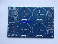
Right now I've been working on finding a PCB board to put the rectifier and the resistors and snubber capacitors so I can use bigger smoother caps mounted separately in the chassis, but I haven't found anything.
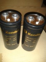
I was thinking that perhaps I can use one of the PSU board I used in my single build, but instead of soldering the smoother caps to the PCB like I did there, I could instead solder some wires to it and connect the bigger caps that way. I have the PCB, rectifier, resistors and snubber cap, I want to get 4 Kendeil 47000uf 50V or perhaps 4 Kendeil 68000uf 50V caps with screw terminals. I have attached pictures of the PCB board I already have and the Kendeil caps I would like to use in this build.
I am planning to use a 24V toroidal with 500VA with this power supply.
Is this possible?.
Thanks.
Hi guys:
I already ordered the components I need for the two LM3886 X3 PCBs from Mouser, some of the stuff I ordered was backordered and I requested the shipment of the complete order to avoid additional shipping charges so is going to take longer than normal for me to get it, but hopefully it will be here soon so we can start putting this thing together.
Right now I've been working on finding a PCB board to put the rectifier and the resistors and snubber capacitors so I can use bigger smoother caps mounted separately in the chassis, but I haven't found anything.
I was thinking that perhaps I can use one of the PSU board I used in my single build, but instead of soldering the smoother caps to the PCB like I did there, I could instead solder some wires to it and connect the bigger caps that way. I have the PCB, rectifier, resistors and snubber cap, I want to get 4 Kendeil 47000uf 50V or perhaps 4 Kendeil 68000uf 50V caps with screw terminals. I have attached pictures of the PCB board I already have and the Kendeil caps I would like to use in this build.
I am planning to use a 24V toroidal with 500VA with this power supply.
Is this possible?.
Thanks.
Attachments
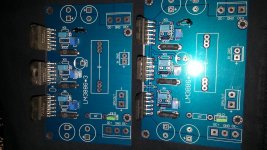
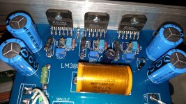
Hi.It has been long time but i am building these.I matched all components around 0,1%
As bypass caps is it better to use elna silmic nichicon muse or a fast low esr cap?Which is more suitable for this?Thanks
As bypass caps is it better to use elna silmic nichicon muse or a fast low esr cap?Which is more suitable for this?Thanks
Attachments
Last edited:
Offset problem
First I soldered all emitter 0r22 resistors but after I read adjustment should be done before connecting 0r22 resistors all together I removed them from solder and measured and adjusted output dc voltages.First and second ones are 0mv but third one is 35mv minimum.When I am turning trimmer clockwise it goes to 65mv. What can I do? Thanks
First I soldered all emitter 0r22 resistors but after I read adjustment should be done before connecting 0r22 resistors all together I removed them from solder and measured and adjusted output dc voltages.First and second ones are 0mv but third one is 35mv minimum.When I am turning trimmer clockwise it goes to 65mv. What can I do? Thanks
Attachments
Last edited:
- Status
- This old topic is closed. If you want to reopen this topic, contact a moderator using the "Report Post" button.
- Home
- Amplifiers
- Chip Amps
- HELP with LM3886 X3 in parallel.