Dear Friends:
I'm back.
I need your help again. I have decided to build an amplifier using some PCB's I got from the auction site, they use three LM3886 chips connected in parallel to produce 150W per channel. I am so happy with the amp I built with your help using one LM3886 per channel that I got really motivated to work on this new project.
I have read something about some amplifiers built by Rowland that use this same design. I'm pretty sure that these PCB's will need modifications, that's why I came here, you guys were super helpful the first time and I am more than satisfied with the quality of sound obtained from the first single chip amp project.
I hope you will help me with this one the same way you did with the other one. My financial situation has improved a little bit since I did the first one, but now I'm facing some bad health issues, I need to keep myself busy now.
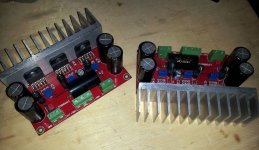
Here is the link for the PCB's I got:
LM3886 x3 150W Amplifier PCB Reliable Design | eBay
Your help is greatly appreciated.
I'm back.
I need your help again. I have decided to build an amplifier using some PCB's I got from the auction site, they use three LM3886 chips connected in parallel to produce 150W per channel. I am so happy with the amp I built with your help using one LM3886 per channel that I got really motivated to work on this new project.
I have read something about some amplifiers built by Rowland that use this same design. I'm pretty sure that these PCB's will need modifications, that's why I came here, you guys were super helpful the first time and I am more than satisfied with the quality of sound obtained from the first single chip amp project.
I hope you will help me with this one the same way you did with the other one. My financial situation has improved a little bit since I did the first one, but now I'm facing some bad health issues, I need to keep myself busy now.
Here is the link for the PCB's I got:
LM3886 x3 150W Amplifier PCB Reliable Design | eBay
Your help is greatly appreciated.
I built two of those from the same vendor. They are still stock as I'v been distracted with other projects. I think it important to better define what improvements you are seeking.
I found the sound very, very close to a single chip design. My initial plan was to use them on the bottom of a bi-amped system thinking the bottom would be improved. There was a little of that but the major feature is their ability to handle 4 ohm speakers.
Please supply additional information describing where you plan to use the amps an what other equipment will be in the chain.
Attachments
Thank you!!!!
Hi:
Thank you all for your prompt responses.
The claim about this being a Rowland design is not mine, again, I'm new to all this, I've read it in some posts on the Internet and the seller of the PCB's I purchased says it on the description.
I want to build another LM3886 based amplifier, if you check here in this site I have another thread, "Bought a XY LM3886....", that was the first project I have ever done, it came out great, the sound quality is excellent, I love my amp, the idea now is to build this one one with the six LM3886, three per channel. I want to see how it sounds, I guess it must sound better since it will be more powerful. In the first project I got help from AndrewT, Pacificblue and others that were very nice and generous to share their knowledge, without their help it would have been impossible.
The XY LM3886 single chip PCB's needed few modifications, the input signal ground had to be separated from the main ground, a capacitor had to be connected in parallel to R4 to filter RF, and a Zobel and Thiele networks were added to the outputs, also some resistor and capacitor values were changed to improve the quality of the sound. All these were suggestions made by AndrewT, Pacificblue and all the other experts that helped me, I couldn't be happier with the final result, the sound is rich and crystal clear.
Regarding this parallel implementation, I've seen some posts here that suggest there is a problem with DC offset, I want to know what to do to avoid that issue. Also, in my previous project I used a single power supply and one toroidal transformer. In this one, should I use a single power supply with one transformer or should I use two power supplies and two transformers?. What's better?.
Also, the builds that I have seen use an additional PCB board to balance the inputs of each of the PCB's, is this mandatory?. If it is, can you suggest the right PCB board for that purpose?.
I'm going to use this amp to drive 4 OHM and 8 OHM speakers, I only need one input, as a source I will use a QLS QA350 Wave Player.
The other issue is that I didn't realize these boards use some SMD resistors, will I be able to solder those myself with a regular solder gun?.
Thank you very much.
The SMD on this board are simply straight forward. Here are a couple video aids, The first one was all I needed to get good results. The second has also been recommended by several builders.
Surface Mount Soldering
Pro SMT Soldering
Surface Mount Soldering
Pro SMT Soldering
The amps do function well as designed, but there is a rather detailed and involved process to match all the DC offsets. There is a good post about it and I will put it up when I find it. For now please look at this site.
This is the base design.
Since it has been mentioned twice on one page, it appears I need to revisit mine after buying some closely matched resistors. You can see in the picture I just used some generics purchased on eBay.
This is the base design.
Since it has been mentioned twice on one page, it appears I need to revisit mine after buying some closely matched resistors. You can see in the picture I just used some generics purchased on eBay.
Last edited:
Here is the link I mentioned containing a balancing process. You might want to brows the entire thread to get a bigger picture.
It's bad Engineering to wire in parallel multiple *voltage* sources.
Even worse if gain and offset depend on yet more external parts, which have their own tolerance spread.
And , by the moment you need to accomodate **33** pins for the active parts, plus all the passives, you might very well build discrete.
All that complexity and troublesome matching for meager 150W/2.6 ohms?
Dear bcmbob, you ask 2 questions in one, I'll answer both separate.")
1) Don't get me wrong, I *love* chip amps, an old dream come true
Impressive sound and specs, simple and cheap, what's not to like about them?
But, of course, they have their ratings (like everything else).
So far, they easily provide *up to* 100W ; more realistically 50 to 70W. Perfect.
Someday they'll make larger ones.
But trying to go beyond that, you must resort to combining them, if possible.
And then they lose their charm, plus creating new problems.
a) parallelling voltage sources is bad Engineering.
Not specific to chip amps, applies to discrete amps too, regulated PSUs, etc.
Being a voltage source and low internal impedance to boot, any slightly higher voltage one will pump lost of amperes into another parallel one (instead of into the load) , trying to make it reach it's own designed voltage, usually both dying at the same time, or at least overheating and working with lots of waste.
Because the other amp will have its own ideas as to what the output voltage should be.
Paralleling 3 certainly won't minimize this, quite the contrary.
b) to prevent (or really, reduce) this, you must obsessively trim and match gain setting resistors, select parts within 1mV offset, etc.
Even so, you *must* add 0.2 ohms in series with each one (negating its high damping and tight control of output voltage) to reduce output-to-output wasted current.
And any part value error, perfectly acceptable anywhere else and well within tolerance, can spell disaster.
c) and even so, the "power increase" is nothing to write home about.
You still have your rail voltage limits, after all.
Stating "150W" on the label sounds good ... learning you'll need nonstandard 2.6 ohm speakers to achieve them is a cold shower.
d) I *do* agree with multiplying power by bridging (one chipamp per side, please )
There you double your effective rail voltage but much more important: you have voltage sources on opposite sides of the load.
In fact, if gain setting resistors on any (or both) of them vary by, say, 10%, nothing bad happens (they certainly do not go up in flames); worst case is that they do not clip at exactly the same time, and you may lose 10% peak voltage. Which anyway you just doubled
Nothing compared to what would happen to parallel amps, same parts tolerance.
2) Complexity.
Chip amps are beautifully simple . Did I mention they sound good?
But if you parallel 3 of them, each of which still needs its own external components as before , you, ... er ... triple the complexity
Plus adding 3 previously unneeded wirewound resistors, needing specially matched parts, being very careful with layout (nobody mentioned this before, but it's a point to be considered), etc.
They quickly lose their charm.
As of simple discrete examples? Tons of them.
Just to mention one, the popular Rodd Elliott P3 amp, if built with robust transistors and higher rail voltage, can easily provide 150W RMS into more useful 8 or 4 ohms loads, standard speaker impedance values, without requiring a 2.6 ohms load.
I have been building Musical Instrument Amplifiers since 1969, over 10000 (yes, ten thousand, not a typo) . Always a dyed in the wool minimalist
Have been using MosFets for 10 or 15 years now, here you have my popular Fahey B300 amplifier, +/- 70V rails, 4xIRFP250 (yes, I still use quasi complementary), 300W RMS/4 ohms.
Built and measured, not simulated.
This is a frame from a You Tube video, by an Argentine Heavy Metal band, who plays with them in Football (soccer in USA) Stadiums and such.
They're using 3 x B300 into 3 x Ampeg 8x10" "fridges".
Yes, they sold their Ampeg SVT Classic tube heads to buy mine.
Here's the video it came from:
Almafuerte - Almafuerte (en vivo) - YouTube
*If* needed, I can draw and post the (very simple) schematic.
1) Don't get me wrong, I *love* chip amps, an old dream come true
Impressive sound and specs, simple and cheap, what's not to like about them?
But, of course, they have their ratings (like everything else).
So far, they easily provide *up to* 100W ; more realistically 50 to 70W. Perfect.
Someday they'll make larger ones.
But trying to go beyond that, you must resort to combining them, if possible.
And then they lose their charm, plus creating new problems.
a) parallelling voltage sources is bad Engineering.
Not specific to chip amps, applies to discrete amps too, regulated PSUs, etc.
Being a voltage source and low internal impedance to boot, any slightly higher voltage one will pump lost of amperes into another parallel one (instead of into the load) , trying to make it reach it's own designed voltage, usually both dying at the same time, or at least overheating and working with lots of waste.
Because the other amp will have its own ideas as to what the output voltage should be.
Paralleling 3 certainly won't minimize this, quite the contrary.
b) to prevent (or really, reduce) this, you must obsessively trim and match gain setting resistors, select parts within 1mV offset, etc.
Even so, you *must* add 0.2 ohms in series with each one (negating its high damping and tight control of output voltage) to reduce output-to-output wasted current.
And any part value error, perfectly acceptable anywhere else and well within tolerance, can spell disaster.
c) and even so, the "power increase" is nothing to write home about.
You still have your rail voltage limits, after all.
Stating "150W" on the label sounds good ... learning you'll need nonstandard 2.6 ohm speakers to achieve them is a cold shower.
d) I *do* agree with multiplying power by bridging (one chipamp per side, please
)There you double your effective rail voltage but much more important: you have voltage sources on opposite sides of the load.
In fact, if gain setting resistors on any (or both) of them vary by, say, 10%, nothing bad happens (they certainly do not go up in flames); worst case is that they do not clip at exactly the same time, and you may lose 10% peak voltage. Which anyway you just doubled
Nothing compared to what would happen to parallel amps, same parts tolerance.
2) Complexity.
Chip amps are beautifully simple . Did I mention they sound good?
But if you parallel 3 of them, each of which still needs its own external components as before , you, ... er ... triple the complexity
Plus adding 3 previously unneeded wirewound resistors, needing specially matched parts, being very careful with layout (nobody mentioned this before, but it's a point to be considered), etc.
They quickly lose their charm.
As of simple discrete examples? Tons of them.
Just to mention one, the popular Rodd Elliott P3 amp, if built with robust transistors and higher rail voltage, can easily provide 150W RMS into more useful 8 or 4 ohms loads, standard speaker impedance values, without requiring a 2.6 ohms load.
I have been building Musical Instrument Amplifiers since 1969, over 10000 (yes, ten thousand, not a typo) . Always a dyed in the wool minimalist
Have been using MosFets for 10 or 15 years now, here you have my popular Fahey B300 amplifier, +/- 70V rails, 4xIRFP250 (yes, I still use quasi complementary), 300W RMS/4 ohms.
Built and measured, not simulated.
This is a frame from a You Tube video, by an Argentine Heavy Metal band, who plays with them in Football (soccer in USA
) Stadiums and such.They're using 3 x B300 into 3 x Ampeg 8x10" "fridges".
Yes, they sold their Ampeg SVT Classic tube heads to buy mine.
Here's the video it came from:
Almafuerte - Almafuerte (en vivo) - YouTube
*If* needed, I can draw and post the (very simple) schematic.
Attachments

I had a thought after reading this thread. I have fancied paralleling chip amps and I realise that it's nowhere near as straightforward as simply building two circuits on one board and paralleling them.
Could one chip be a slave to the other chip? That way there'd be no "fighting" between the chips. Small tolerance differences wouldn't cause major problems with such a configuration.
Could one chip be a slave to the other chip? That way there'd be no "fighting" between the chips. Small tolerance differences wouldn't cause major problems with such a configuration.
I had a thought after reading this thread. I have fancied paralleling chip amps and I realise that it's nowhere near as straightforward as simply building two circuits on one board and paralleling them.
Could one chip be a slave to the other chip? That way there'd be no "fighting" between the chips. Small tolerance differences wouldn't cause major problems with such a configuration.
If you use two chips you could bridge them.
If you use two chips you could bridge them.
Of course, but this thread is about more current, not more voltage.
do a search Fast Eddie D... it's been done.
_-_-
I did a search and found discussions but no example circuit. I think I could figure it out on my own, though.
How about this- 2 x 3 or 2 x 4 3886 parallel/ bridged? If you used a slave circuit, you could skip the lossy output resistors. I can think of a few advantages to a circuit like this, like full bridged voltage swing into 4 ohms with 2 x 4 parallel/ bridged.
There are some other advantages too.- Status
- This old topic is closed. If you want to reopen this topic, contact a moderator using the "Report Post" button.
- Home
- Amplifiers
- Chip Amps
- HELP with LM3886 X3 in parallel.