No, I didn't need it yet. Looks fine though.
Either of those parallel boards could use this schematic, except that the 3-chip model would have a 100uF bootstrap cap.
My 70's receiver-amp refit project has a custom fit center tap transformer, previously powering 55 watts per channel with frail discrete amp, now powering 90 watts per channel with the durable 2-chip TDA7293 parallel boards. Due to the transformer amperage capacity, I didn't need the 3-chip boards at this time. And, now I find out that the smaller 2-chip parallel units easily exceed the capacity of my speakers.
P.S. I bought a box of TDA7293 chips to play with for parallel amp point to point projects, so it is unlikely that I'll need boards for some time. More powerful speakers probably comes first.
Daniel,
Thank you for you comments. Interestingly. P to P is very probably very "doable" with these amp since they are so compact and do not need that many components.
Keep us posted!
Regards,
What to do with those bad layout single-layer boards? Probably this:
To get a nice sound from the TDA7294 treble, my older design is like this:
Gain divider: Feedback resistor 114k vs Feedback-shunt resistor 2.7k
Signal caps: NFB-shunt cap 243u, input cap 0.68u and a tiny polyester bypass for both
Power caps: 220u per rail (can add either diode isolators or rail to rail cap)
Input: either blarebuster 1 or lightspeed attenuator
That can be used with:
Poor Layout boards can use it well, due to the different harmonics.
If you want 6-1/2" and smaller speakers to play clear and Very loud.
Point to point builds, easier to build with the tiny size capacitors.
Concert duties for little monitors or for multichannel midrange & treble arrays.
A sound reinforcement favorite for many years, that older design, is sensitive and has a different sound. if there's one special combination of cap and resistor values that you can plug in to a bad layout single layer board to cause it to sing or be useful, this is it. Component values described at the top of this post.
Alternatives:
If the above doesn't do it, then I'd suggest one or both of the following options:
1). Throw the board away and use the chip point-to-point, aka no board sound at all.
2). Or use this much cleaner sounding board, since compact dual-layer sounds like point-to-point.
Notes:
The majority of "amplifier tone sounds" is not in the chip, but actually most of the tone variances are from board layout and power circuit, especially power layout of the amplifier board and the "fix" for that is selecting a really favorable board.
Last edited:
AComplete audio amplifier with TDA7294
Hi guys!
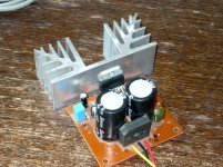
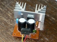
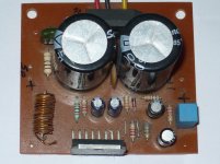
Here I've made audio amplifier with TDA7294 and it works great!
This amplifier is complete with power supply!")
Greaz of 8A and 600V
2 electrolyte of 4700uf/50V.
I enjoy the sound!!
cheers!
Hi guys!
Here I've made audio amplifier with TDA7294 and it works great!
This amplifier is complete with power supply!
Greaz of 8A and 600V
2 electrolyte of 4700uf/50V.
I enjoy the sound!!
cheers!
Attachments
PCB layot is in Protel 98Very interesting! That's Surprisingly compact for single layer! Do you have PCB layout photos for it?
Can you open it and then hit printscreen, paste into photo editor, and then make screenshot photos of the layout?PCB layot is in Protel 98
<<<<< snipalot
2). Or use this much cleaner sounding board, since compact dual-layer sounds like point-to-point.
end snip >>>>>>
Hi Daniel !
Interesting. Are you endorsing this particular board / supplier?
I am not trying to catch you out, it's just that it would be nice to identify a good, low cost and trustworthy chipamp kit. It might benefit a few people to know.
Rgds,
blakkintosh
Yes, I have been endorsing a very compact layout for cleaner power, And parallel amp for enhanced output device linearity. That means, Compact Parallel amp is the highest quality for TDA7293. So I contacted Zoe Tsang (Not a financial affiliate) and requested this listing: Two board *stereo* kit TDA7293 Parallel amplifier
And I made this schematic.
And I made these assembly photos.
It is also in my signature line.
When using my schematic, power circuit and power supply:
Dynamics: Exaggerated and/or High End (suitable for music replay)
Tone: Very High End--maintains pleasant tone all the way to the rails
Clarity: It could beat an STK, probably (better than a midfi)
Power: 70 watts to 8 ohms, 90 watts to 4 ohms, 130 watts to 4 ohms
Usage: The dance floor of a pub or a small nightclub (big houses too)
Double check: This amplifier is not suitable for critically dissecting music for an autopsy/analytics. And despite the pleasant tone and deceptively small size, the little thing is extra powerful, so it is not suitable for apartment dwellers because the neighbors will hear it. All of them. However, it can do enthusiastically well for fun, loud, and lively concert sound.
Last edited:
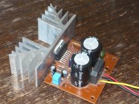
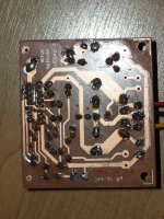
Rear of PCB,...PCB-top,...Can you open it and then hit printscreen, paste into photo editor, and then make screenshot photos of the layout?
Attachments
Last edited:
4700mf capacitor is not at all enough for this chip amp. minimum is 10000mfd.considering the output mosfets.
a short length of cable from power supply to amp board acts like choke filter which I always found healthy in all my amps,which means I will keep the Ac diodes far away from chip.
what I mean is, one should try connecting the scope to power lines and see with music on.
a short length of cable from power supply to amp board acts like choke filter which I always found healthy in all my amps,which means I will keep the Ac diodes far away from chip.
what I mean is, one should try connecting the scope to power lines and see with music on.
>>> snipola
So I contacted Zoe Tsang (Not a financial affiliate) and requested this listing: Two board *stereo* kit TDA7293 Parallel amplifier
And I made this schematic.
And I made these assembly photos.
It is also in my signature line.
<<<< exit snipolito
Daniel,
Thanks for that clarification. I have bought a few fleabay amps over the years and board layouts have varied from good to appalling.
Nice to find a good one !
Kind regards,
Keith Arnold
blakkshepeaudio
TDA7294 with dc protection
I wonder what they tried to achieve making this extra extensive layout.
ne5532 as dc servo
? Ne5532 as voltage comparator for lm317.
.What is that 470ohm, 0.5 ohm and 7.5k doing near the speaker ?
Hi all,
Nice work Daniel and all who contributed to this great thread...
I have one simple question about the schematic in post 461...
http://www.diyaudio.com/forums/atta...mizing-tda7294-output-tda7294-adjustable2.gif
what is the purpose of the 220pF capacitor between the input pins? is it RF filtering? and what sonic effect does adding this capacitor have and the effect on the phase and magnitude of input signal like tyger23 mentioned in post 470?
Best regards.
Nice work Daniel and all who contributed to this great thread
...I have one simple question about the schematic in post 461...
http://www.diyaudio.com/forums/atta...mizing-tda7294-output-tda7294-adjustable2.gif
what is the purpose of the 220pF capacitor between the input pins? is it RF filtering? and what sonic effect does adding this capacitor have and the effect on the phase and magnitude of input signal like tyger23 mentioned in post 470?
Best regards.
It is to discourage RF. This is especially useful in the case of computers since would wouldn't want attempt amplifying the noise of a source that runs on extremely convoluted mess of a power circuit. Actually an inductor based filter would certainly work better, but it would not be so simple nor as inexpensive as the 220pF.I have one simple question about the schematic in post 461...http://www.diyaudio.com/forums/atta...mizing-tda7294-output-tda7294-adjustable2.gif what is the purpose of the 220pF capacitor between the input pins? is it RF filtering?
Testing input through output will show nothing other than you put in the cap, but this does not change any audible aspects of the amplifier. 330pF is also okay.and what sonic effect does adding this capacitor have and the effect on the phase and magnitude of input signal like tyger23 mentioned in post 470?
Although I loved the older production TDA7294, I absolutely hate the new production. So, unless you've got some new old stock sitting around, I'd recommend to avoid new TDA7294 new version craptastic waste of time. Instead of that, go with TDA7293's--those still sound a lot like they're supposed to.
50v, 63v, 83v, 100v are all suitable.Another question...What is the voltage rating for the bootstrap capacitor?
It is to discourage RF. This is especially useful in the case of computers since would wouldn't want attempt amplifying the noise of a source that runs on extremely convoluted mess of a power circuit. Actually an inductor based filter would certainly work better, but it would not be so simple nor as inexpensive as the 220pF.
Spot-on Daniel thanks a lot for the detailed explanation.
Although I loved the older production TDA7294, I absolutely hate the new production. So, unless you've got some new old stock sitting around, I'd recommend to avoid new TDA7294 new version craptastic waste of time. Instead of that, go with TDA7293's--those still sound a lot like they're supposed to.
Again you read my mind
i have some NOS chips (to avoid the fakes) and a huge anodized heat all i need now is a good layout and i will give it a go. By the way i am going with your version named "TDA7294-Adjustable2" with some minor mods, I'll tell how it sounds as soon as i am finished.Thanks and best regards.
Guesstimation table for new production chips:
V7 TDA7293 = Real higher cost TDA7293
V6 TDA7293 = Real low cost TDA7294H (max 25+25vac transformer)
TDA7294 = TDA7295 or dirt cheap cull (terrible audio quality)
TDA7295 = TDA7295 or dirt cheap cull (terrible audio quality)
TDA7296 = Real TDA7296 OR a cheap substitute
This also affects authorized vendors. The ST chips that I have purchased from Mouser and Digikey have been identical to those in the eBay kits.
You really can buy an old-production quality TDA7294; but, it won't have "TDA7294" printed on the casing, AND all 15 pins will work.
Attempting to purchase TDA7296's sometimes works, and I guess that is because old stock of the less popular chip hasn't run out yet.
My above post has an error. It is actually TDA7294S that has all 15 pins working. That chip is great. It can be labeled as TDA7293 in cheap kits. Sounds good, but has TDA7294's voltage and load maximums. If the whole kit costs less than TDA7293's, then I think that 25+25vac transformer is maximum. Otherwise, those things work great. They're a lot better than new production TDA7294's.
One missing trick!
It needed a variable input load since 22k images better but with Louder Mids and 27k has softer pleasant mids. That probably needed to be a variable resistor for the slight fine tuning that could be done with it.
From years and years ago, here's an alternative: My old chip has 100k feedback, 2k7+220u feedback shunt, 36+36vdc rails (if you have less voltage likewise decrease the gain too), and is otherwise similar to the newer schematics. I like the lighter current at small signal area for its prettier midrange and treble and decent imaging; however, it is not as bassy. Both adjustable input load and the BlareBuster circuit can work with it, for relatively easy fine tuning of the input impedance that is and isn't.
P.S.
If you decided to separate the rails, protect the small signal voltage amplifier's power pins with MBR1645 schottky so that they can't go more than 1/3rd of a volt lower voltage than the output buffer's power pins. This approach is listed on some "hi fi version" schematics online but the chip breaks if lossy diodes are used for the safety bypass. SO, I suggest upgrading the BY fast silicon to MBR schottky on those separate rails schematics. I didn't publish any like that, because actually doing it right is more complicated than building a better discrete amp, and half measures don't outperform the simplified bus rail system shown on my schematics.
P.P.S.
These chips explode immediately if the bootstrap cap is backwards or a bad cap. Might want to give that thing a quick checkup before powering on. Or the easy way--a 33u Nichicon ES, which is good quality and never backwards.
Sort of a made for a "big" sound arrangement. The adjustable gain is needed to find an ideal gain setting which varies by power voltage. The sweet spot isn't really findable with fixed resistor values.By the way i am going with your version named "TDA7294-Adjustable2" with some minor mods, I'll tell how it sounds as soon as i am finished.
One missing trick!
It needed a variable input load since 22k images better but with Louder Mids and 27k has softer pleasant mids. That probably needed to be a variable resistor for the slight fine tuning that could be done with it.
From years and years ago, here's an alternative: My old chip has 100k feedback, 2k7+220u feedback shunt, 36+36vdc rails (if you have less voltage likewise decrease the gain too), and is otherwise similar to the newer schematics. I like the lighter current at small signal area for its prettier midrange and treble and decent imaging; however, it is not as bassy. Both adjustable input load and the BlareBuster circuit can work with it, for relatively easy fine tuning of the input impedance that is and isn't.
P.S.
If you decided to separate the rails, protect the small signal voltage amplifier's power pins with MBR1645 schottky so that they can't go more than 1/3rd of a volt lower voltage than the output buffer's power pins. This approach is listed on some "hi fi version" schematics online but the chip breaks if lossy diodes are used for the safety bypass. SO, I suggest upgrading the BY fast silicon to MBR schottky on those separate rails schematics. I didn't publish any like that, because actually doing it right is more complicated than building a better discrete amp, and half measures don't outperform the simplified bus rail system shown on my schematics.
P.P.S.
These chips explode immediately if the bootstrap cap is backwards or a bad cap. Might want to give that thing a quick checkup before powering on. Or the easy way--a 33u Nichicon ES, which is good quality and never backwards.
Last edited:
- Status
- This old topic is closed. If you want to reopen this topic, contact a moderator using the "Report Post" button.
- Home
- Amplifiers
- Chip Amps
- Optimizing TDA7294 Output