For driving woofers, you're looking for a bridge amp.Also mention if i could use 18-0-0-18 transformer
I desire an output of at least 50W across my 8ohm woofers
If ~45 watts won't do, then you need to escape the limiter by using the parallel board from my signature line. It is worth about 90 watts. Bridge that thing.
P.S.
Per your other requests, we are currently working on an optimized schematic for full bandwidth amplifier, but I am momentarily stuck.
Help! Engineer assistance needed! I'm stuck at 40X. Need comp.
Sounds beautiful at approximately phase linear, but I've got a problem: With the most appreciable treble and highest resolution and other beneficial practicalities occurring when the gain is set about 40X, I believe that this amplifier has requested compensation.
Probably the front end section is naturally a lot faster than the unity output section (speed crippled output section), and that limitation is exactly like nailing a 2x4" board across the doorway at 5.5 foot height so that a 6 foot tall person gets a nasty surprise when he runs through that door. That's what slow outputs do. Apparently, that is the cost of decreased external component count convenience for chip amplifiers. This amp runs optimally at only ONE speed, and selecting this by gain alone results in too high gain of about 40X.
It may be a chip, but sealed inside is an antique. This chip is a grandma AF design, not a triathlete RF design. If grandma runs too fast, she falls down. And, using gain as the sole means of speed selection, is not optimal.
If we try to make an RF amp out of this thing and also expect quality audio, I think we'll be stuck to the end of time, so let's please take the shortcut of making it do what it can for audio.
Question:
Can you tell me how to install a compensation, plus some ballpark values that will produce the desired behavior, relocated to a gain of about 32X? Without comp, I'm stuck at 40X. Help?
P.S.
I'd like a really simple and small size comp that won't confuse constructors or make the boards look like exploded Christmas tree. I did one of those already and it is not explainable for building.") If I had an especially doable / installable compensation example, then I can simply install it, run the gain up to coarse/clinical (too slow), turn the gain down to peakish/nasty (too fast), and find the middle ground of the just right speed for pretty hi-fi like strong wind. After that I can compare different current settings all set to the same/similar gain factor--wow, so much easier!!
If I had an especially doable / installable compensation example, then I can simply install it, run the gain up to coarse/clinical (too slow), turn the gain down to peakish/nasty (too fast), and find the middle ground of the just right speed for pretty hi-fi like strong wind. After that I can compare different current settings all set to the same/similar gain factor--wow, so much easier!!
Well, I can do it after I replace the poor soldering iron--I already had to rewind the broken coil once and now the tip is worn down to a stubby little nub.
I'm testing on the TDA7294S/TDA7293 parallel board (one chip drives two) in my signature line because you guys wanted to do 4 ohm speakers, bridged projects, and I assume that you wouldn't want to listen to a limiter set to ~45 watts (of bass) on the solo chip, so I'm using the 90W board.
The small signal area seems to do identically to a single chip board, except that the bootstrap cap for parallel amp is 100uF, the sole difference. I DO have the feedback and feedback-shunt resistor on trackside, direct-connect to the chip, in order to dodge board layout tone differences. I can sure check both solo and parallel, but 40X for phase linear speed match behavior is not convenient. I'd like to try the gain of 32X to see if that's better. I can't do that without comp. Please get me unstuck?
P.P.S.
Meanwhile, I'm off to review the huge STK thread where a different miller amp was re-adapted to run at lower gain via external comp. That's a different amplifier, so I don't know if the same thing can be pasted onto the TDA729X chip.
Sounds beautiful at approximately phase linear, but I've got a problem: With the most appreciable treble and highest resolution and other beneficial practicalities occurring when the gain is set about 40X, I believe that this amplifier has requested compensation.
Probably the front end section is naturally a lot faster than the unity output section (speed crippled output section), and that limitation is exactly like nailing a 2x4" board across the doorway at 5.5 foot height so that a 6 foot tall person gets a nasty surprise when he runs through that door. That's what slow outputs do. Apparently, that is the cost of decreased external component count convenience for chip amplifiers. This amp runs optimally at only ONE speed, and selecting this by gain alone results in too high gain of about 40X.
It may be a chip, but sealed inside is an antique. This chip is a grandma AF design, not a triathlete RF design. If grandma runs too fast, she falls down. And, using gain as the sole means of speed selection, is not optimal.
If we try to make an RF amp out of this thing and also expect quality audio, I think we'll be stuck to the end of time, so let's please take the shortcut of making it do what it can for audio.
Question:
Can you tell me how to install a compensation, plus some ballpark values that will produce the desired behavior, relocated to a gain of about 32X? Without comp, I'm stuck at 40X. Help?
P.S.
I'd like a really simple and small size comp that won't confuse constructors or make the boards look like exploded Christmas tree. I did one of those already and it is not explainable for building.
If I had an especially doable / installable compensation example, then I can simply install it, run the gain up to coarse/clinical (too slow), turn the gain down to peakish/nasty (too fast), and find the middle ground of the just right speed for pretty hi-fi like strong wind. After that I can compare different current settings all set to the same/similar gain factor--wow, so much easier!! Well, I can do it after I replace the poor soldering iron--I already had to rewind the broken coil once and now the tip is worn down to a stubby little nub.
I'm testing on the TDA7294S/TDA7293 parallel board (one chip drives two) in my signature line because you guys wanted to do 4 ohm speakers, bridged projects, and I assume that you wouldn't want to listen to a limiter set to ~45 watts (of bass) on the solo chip, so I'm using the 90W board.
The small signal area seems to do identically to a single chip board, except that the bootstrap cap for parallel amp is 100uF, the sole difference. I DO have the feedback and feedback-shunt resistor on trackside, direct-connect to the chip, in order to dodge board layout tone differences. I can sure check both solo and parallel, but 40X for phase linear speed match behavior is not convenient. I'd like to try the gain of 32X to see if that's better. I can't do that without comp. Please get me unstuck?
P.P.S.
Meanwhile, I'm off to review the huge STK thread where a different miller amp was re-adapted to run at lower gain via external comp. That's a different amplifier, so I don't know if the same thing can be pasted onto the TDA729X chip.
Last edited:
Question:
Can you tell me how to install a compensation, plus some ballpark values that will produce the desired behavior, relocated to a gain of about 32X? Without comp, I'm stuck at 40X. Help?
I already explored compensating the TDAXXXX for lower gain, and it was not practical for reasons we already discussed. It's just too slow. However, you might experiment with shelving the gain so that it has 40x gain at maybe 100 kHz and lower gain at audio frequency. There will probably be caveats that you will have to triage.
Start with the Bode (or quasi Bode) plot, then superimpose the theoretical closed loop gain on top of the Bode plot. If they intersect with a slope of 6 dB an octave and the intersection doesn't lie close to slope transitions or crazy parts of the curve, it'll most likely be stable. Whether it provides an improvement or not is something you will have to decide. Looking at the superimposed graphs should give you some ideas on how to optimise your compensation.
Use a snubber on the output.
I credit Walt Jung for this technique. Back in the day it was the only way to get decent and practical audio performance out of the few choices of fast and cranky opamps.
I did just try that resistor from in+ to in-. This was not desirable. As I turned the dial, it cut all the resolution out of the treble first and then it made the mids quiet and a bit mucked. Well, that doesn't work.
SO, do you have an example of "shelving the gain" ???
Standard treble booster with a much smaller cap? Like add a little RC parallel to the feedback-shunt RC? The combined value hits the 40x mark, but there's not 40x in the audio band. Do I do it like that?
P.S.
Found another nice spot: 27k vs 680 and that's perhaps slightly cleaner and more level than the previous. It did "energetic efficiency" artifact too but this time with somewhat better bass. At full blast, which is quite the shock with flip your chair power, the heatsink would not warm your coffee.
Last edited:
SO, do you have an example of "shelving the gain" ???
Standard treble booster with a much smaller cap? Like add a little RC parallel to the feedback-shunt RC? The combined value hits the 40x mark, but there's not 40x in the audio band. Do I do it like that?
You've got it, Daniel. Stay as far away from the audio band as you can. 100 kHz min, 200 kHz better. The low gain will probably constrain you to a lower turnover frequency unfortunately. The higher the turnover frequency, the less the shelving circuit will affect the audio band (to 20 kHz).
And snub the output. Your creation will probably have high gain at RF and your speaker wires will be like an antenna.
And don't forget the RF input filter.
Look at the Bode plot, think about what you want to do, and pick an intersection that will provide a 6 dB/ octave slope at the intersection and that provides as high a turnover frequency as practical. Is that frequency reasonably high? Then you might have something to work with.
I ordered the same kit from Jim's Audio and I plan to build a modded stereo amp. I have read this entire thread over a number of times and I ask that you check my understanding before I heat up my soldering iron.
I have a 25v dual secondary xfmr of 330va. A little strong but that's what I have. I will constrict the pwr supply as described in posts 116,117.
On the circuit boards I will:
1) replace the 22uf/50v supply caps with 220uf/50v Panasonic FC electrolytic
2) Replace the 47uf/35v input cap with 660uf/35v electrolytic
3) Replace the 680ohm feedback resistor with 1.2k ohm 1/2w Xircon carbon film
4) Replace the 22k NFP shunt resistor with 47k 1/4w Xircon carbon film
I'll be using a pre amp because I've got a few laying around collecting dust.
Fused mains, star ground, bulb tester, speaker protection will be employed.
Am I on the correct track?--Just trying to summarize at this point. Thanks!!
Still going. . .
33k vs 1k2, Fail, muffled treble
33k vs 1k0, Borderline, slight treble droop, Loud bass, good res, big img, choked@85%
33k vs 820, Borderline, slight treble droop, Loud bass, adeq res, good img, choked@75%
27k vs 820* Valid, level sound, Loud bass, good res, big img, choked@95%
27k vs 510+220 (730)* Valid, level sound, Loud bass, High res, Big, img, no clip, armstrong
27k vs 680* Valid, nearly level sound, big bass, High res, big img, no clip, high power
25k vs 680, Valid, level sound, loud bass good res, adeq img, no clip
22k vs 680, Borderline, tolerably forward, big bass, good res, adeq img, no clip
22k vs 560, Valid, tolerably forward, big bass, good res, big img, choked@95%
Aha!
I just tried an old trick, and it worked. Got the gain down a bit, while the audio performance and power went UP. Series carbon resistors for feedback shunt, Like this:
27k vs 510+220+660u
Wow, everything nicer.
This step got the gain from 40x down to 38x, but energetic efficiency, resolution, imaging, all got better, while the audible response also got more level, some better bass and the treble is pretty. This time there was enough bass for X-max. Running cool, and well. Like it!
That transformer is perfect.I ordered the same kit from Jim's Audio and I plan to build a modded stereo amp. I have read this entire thread over a number of times and I ask that you check my understanding before I heat up my soldering iron.
I have a 25v dual secondary xfmr of 330va. A little strong but that's what I have. I will constrict the pwr supply as described in posts 116,117.
On the circuit boards I will:
1) replace the 22uf/50v supply caps with 220uf/50v Panasonic FC electrolytic
There was a minor layout change. Instead of the MBR1035 schottky going at the output end of the power supply board. . . they go at the power terminals of the amplifier board(s). What they do is hard to explain, but their task is rather simple--they block blur. And, I have been using them during the testing.
Most remarkably, I didn't have to roll off the bass with tiny size caps at amplifier input; but instead of bass blocking, the Schottky already blocked the blur at powerside, so then I was free to allow more bass into the amplifier with any size input cap. I put it up to 5uF to check it out. Doesn't blur.
Looks daft but works exactly as intended. Applicable parts include:
MBR735, MBR745, MBR1035, MBR1045, MBR1635, MBR1645. Two schottky (1 for v+ and 1 for v-) per each amplifier board.
Without the shottky, the amplifier fuzzed and faltered at full blast; However, with the shottky, the amplifier did not either falter or clip. Paradigm shift is amplifier board power decoupling forced to work in wide conditions, without the labor of arrays--The schottky is easier and effective. They promoted greater peak power, suitable for audio amp. Also, most efficient way for decreased crosstalk in stereo builds, per KSTR's comment, post 117.
Yes, Panasonic 220u is a okay. Their 270u is fine too. You can also parallel caps if you want to explore that for a slight boost with slightly different tone.
I actually got lower distortion with: 27k vs 510+220 (post#408)2) Replace the 47uf/35v input cap with 660uf/35v electrolytic
3) Replace the 680ohm feedback resistor with 1.2k ohm 1/2w Xircon carbon film
4) Replace the 22k NFP shunt resistor with 47k 1/4w Xircon carbon film
But most importantly, put the feedback resistor trackside, under the board, right onto the chip pins.
The 510+220 (730) is carbon. Alternative is 560+150 (710).
I used the xicon carbon film from the radio shack--those have nice thick low inductance pins, not wispy pins. On the Jim's Audio single sided board, just put one resistor each hole at the spot marked 680, and tie the tops of the resistors together to create your 730R or 710R.
Or, on the Parallel board, put these resistors trackside, directly from pin2 to NFB-shunt cap so that you don't amplify the weird PCB layout.
The nfb-shunt cap(s) will end up hanging off the left edge of the board if you happen to use multiple parallel caps and or bypasses. However, 680u(16v)+0.47u(Nichicon ES), both electrolytic, will fit onto the board.
The very large value nfb-shunt cap also needs a safety clipper. You get a pair of diodes, such as 1n914 or 1n4148, and put the pair together antiparallel (paralleled with stripes facing opposite directions). That makes a clipper. The forward voltage drop is now ~0.65v in both directions. This clipper is used to prevent the 660u cap from charging up to a blast that could knock out the -input. When the antiparallel diodes are put parallel to the 660u, they limit the cap charge to ~0.65v. This also prevents power on thumps.
Notes: Without the safety clipper, the extra big size NFB-shunt cap will probably cause a thump. Use the clipper--That clipper does not clip audio. If your rails are lopsided, use two series clippers (4 diodes) for 1.3v tolerance, which is still better than nothing. Then the NFB-shunt cap will not accidentally charge to more than 1.3v. The big caps can work fine, but is slightly more effort. It is the price of good bass.
Maybe you'd like to wait until I've made some photographs?
Alarm clock for waking deaf teenagers? Right on! The dynamics could be interesting.I'll be using a pre amp because I've got a few laying around collecting dust.
I did not use a preamp because I don't want to require everyone to build exact same model preamp--that plan failed last time. So, for repeatable results, this time, I used direct drive from a computer, a commonplace application that is widely available.
Last edited:
Progress report, general
I see that Pilot Test model Honey Badger discrete amp runs 42X gain on 40v rails. However, we've got 38X gain on 35v rails. Close enough. The design goal on this TDA7294 thread was for simple high performance. And sure, high gain (turbo) amplifier needs a better power supply. We did that already.
No problem.
Previously, I kept searching for the one condition where turning down the gain also turned up all of the the fidelity aspects and power. Got it. The amplifier behavior conforms to the design goals. Gain setting is 27k vs 510+220 for 38X. Uncomplicated. Tis done.
Time to play with other parts, such as the +input of the little single board.
Progress report, Parallel 140W & Bridged Parallel 260W, 500W
Currently, I've been using the parallel TDA7294S/TDA7293 board because of all the Bridged discussion, and I used the parallel board because sturdy parallel amp has a higher success rate than than transformer instructions and the parallel board has less audio problems with the on-chip limiter.
The strong Parallel board is ready for your Bridged project with either 2-chip model for 8 ohm speakers or 5-chip model for 4 ohm speakers. For bridge amp, notice that the MBR shottky block power loss at the upswing amp board while the downswing amp hits the bass, and vice versa, so that peak power performance and clarity is maintained at a high level, per each board. The effort is not much different from a simple stereo amp. Feel free to use nice buffers to build really rockin bridge adapters. Simple bridge also works. Resolution and tone varies by input load and input impedance, so tweak your bridge adapter outputs and amplifier input load (12k?) nicely, for low noise. I don't have the quarter kilowatt capable 8 ohm speaker or half kilowatt capable 4 ohm speaker for which to test this amp. See also Bob's bigger size edition of the power supply design. Clip indicator pin can drive a transistor, which can drive a voltage divider, with 10u load at output, which can drive the exact same model of 50k LDR optocoupler used in 50K version of Lightspeed attenuator, so that you get a VoluMax boost (1 unit per each board) and decent protection against excessive clipping current, without blocking initial bass impact. For bridged parallel amp, it may be needful to synchronize the mute and standby functions to a central location.
I'm not building the Bridge Parallel amp--unnecessary for use in my house.
Or, for something much easier, the Parallel board is ready to drive your 4 ohm speakers.
I am re-fitting a nice old receiver with this 4 ohm drive capacity, just the simple parallel amplifiers.
Progress report, Single
Up Next, I'm doing the +input work on the single TDA7294V with that Jim's Audio board, and will re-check the other details too. The input components are a bit more predictable with the solo chip, probably cap on the wrong side of non-zero output impedance source, so I'm planning to do automatic current drive input for it with a few passive parts, as simply as possible.
Let me catch my breath and switch boards.
With the little single board, I'll do some photographs for you.
After that, possibly some schematics, if I'm not completely tuckered by then. Performance first, schematics later, so that the performance gets onto the schematics.
Last edited:
Nice work, Daniel. I would like to ask a few questions about your resistor selection and make a couple of comments.
You keep talking about using carbon resistors. I have heard this before. I have been looking at 0.1% resistors for my parallel amp. There is a variety and the prices vary quite a bit. Have you looked at the thermal drift specs on the resistors you are using? Some precision resistors have one tenth the thermal drift of ordinary 1% resistors! And there are two sources of heat the resistors are subject to: the ambient environment (which can get quite hot if the resistor is mounted near the chip), and the heat generated by the signal on the resistor. This may seem like hairsplitting, but consider this: a 10K and a 1K resistor in series in the feedback loop essentially carry the same current. The 10K resistor will be subject to 10 times the thermal drift from the signal generated heat! This can be mitigated of course by making the resistors bigger (but not too big ). So these are all things to think about when selecting parts and planning layout.
You keep talking about using carbon resistors. I have heard this before. I have been looking at 0.1% resistors for my parallel amp. There is a variety and the prices vary quite a bit. Have you looked at the thermal drift specs on the resistors you are using? Some precision resistors have one tenth the thermal drift of ordinary 1% resistors! And there are two sources of heat the resistors are subject to: the ambient environment (which can get quite hot if the resistor is mounted near the chip), and the heat generated by the signal on the resistor. This may seem like hairsplitting, but consider this: a 10K and a 1K resistor in series in the feedback loop essentially carry the same current. The 10K resistor will be subject to 10 times the thermal drift from the signal generated heat! This can be mitigated of course by making the resistors bigger (but not too big
). So these are all things to think about when selecting parts and planning layout.Hi Eddie,
The resistors that came with the kits have hair fine wispy leads, so I threw them away--either low end junk or high end zoot would change the component values and compensations, and doesn't promote repeatable results. Therefore, I suggest upgrading the signal path to high quality normal-behaving carbon film resistors from Xicon, Vishay, and Koa Speer, for the simplicity that helps promote a normally behaving amplifier, and a schematic with repeatable results.
The carbon comp or film is ideal for base stopper, but transistor base locale is unannounced with chips, so I thought it convenient to avoid inserting random metal resistors at extra cost. I've already been dodging some metal PCB traces. Probably it was also helpful to route the good quality normal-behaving resistors as directly and simply as possible--a miniscule amount of point to point underneath the board, avoids PCB layout influence on performance.
Other than these factors, I cannot identify if the old school tricks or exactly right value helped more, because it was both.
P.S.
So, I start up the parallel amp today and think "gosh that's good" and then I check to see if the computer EQ was turned on. It wasn't.
Meanwhile, onto making the little solo board do its job. . .
Let's see what happens.
Antsy TDA7294 single layer board. . .
Here's the single sided TDA7294 board available Jim's Audio and elsewhere. I believe this resistor re-route configuration and values are correct; and I hope to test this one fairly soon. All of the resistors are on the board and by shortest route, so if you don't want any trackside work, this is probably the way to go.

Howabout a trip to the nearest Radio Shack for:
"Micro 1A Diodes" such as 276-1104 or 276-1101. This is to restrict charge build-up in the giant NFB-shunt cap. Assuming 2 boards, you'll need 4 standard silicon diodes if your rails are level, or 8 diodes if your rails are not level.
Excellent flux, such as 64-022. This is to convert non-shiny imperfect solder joint to perfect solder joint--apply drop of flux and re-heat. Perfect, and quickly. Excess washes off with alcohol.
500-Piece 1/4-Watt Carbon-Film Resistor Assortment, 271-312. This is a big collection of very good quality resistors, and exactly what I've used. They're similar to other quality parts like Xicon, Vishay, Koa.
And they've got thermal compound, Arctic Ceramique, which is excellent for chip amplifiers.
Also consider purchasing the three Smallest sizes of tiny green polyester dip cap. That's for use as bypass helpers to larger signal caps. They work very well to bypass an Elna Cerafine of 4.7uF and Smaller sizes for simulating BlackGate sound without the wallet smash effect. Anyway, these little green polyester caps from the Radio Shack can help remove treble droop from larger signal caps. They're slightly lossy, and therefore far less risk of ringing if you install a mismatch; so, they're easy to use for bypass duties. I believe the packages are marked 0.047uF, 0.022uF, 0.010uF
You may also want to experiment with Radio Shack's big blue 1uF as input cap, although not exactly my preference to use HV plastic for signal, it is well reviewed and there is no need to pay more for that approach--although possibly not optimal, at least it does not treble droop, so it is not confusing to use it. The main benefit is that it will give you an option for comparing.
Elsewhere:
When you order your 220u and/or 270u amplifier board power caps, consider getting a small variety. It is quite likely that you will want to do some comparing for quality control. No need to compare everything under the sun--a tiny amount of 220u, 270u, Panasonic FC, Nichicon FW, 50v caps will do.
If the same online vendor, such as Mouser, happens to have Nichicon ES, 0.47uF and 1uF sizes, get those too, because they're extraordinarily easy to use for bypassing larger electrolytic signal caps, such as your Nfb-shunt cap. These two smallest sizes of Nichicon ES bipolar cap are so small that they won't treble droop within the audio band. They're high resolution and generally work well, so that's not confusing to use.
If the kit didn't come with thermal pad/mica or shoulder washer, you'll be wanting those too.
Here's the single sided TDA7294 board available Jim's Audio and elsewhere. I believe this resistor re-route configuration and values are correct; and I hope to test this one fairly soon. All of the resistors are on the board and by shortest route, so if you don't want any trackside work, this is probably the way to go.
Antsy? That's good news! I have a suggestion. . .Thanks for the helpful reply Daniel. I will await your photos and last changes before ordering parts for the boards and pwr supply so I can incorporate your changes. I am getting antsy to begin the build and will keep my progress posted.
Howabout a trip to the nearest Radio Shack for:
"Micro 1A Diodes" such as 276-1104 or 276-1101. This is to restrict charge build-up in the giant NFB-shunt cap. Assuming 2 boards, you'll need 4 standard silicon diodes if your rails are level, or 8 diodes if your rails are not level.
Excellent flux, such as 64-022. This is to convert non-shiny imperfect solder joint to perfect solder joint--apply drop of flux and re-heat. Perfect, and quickly. Excess washes off with alcohol.
500-Piece 1/4-Watt Carbon-Film Resistor Assortment, 271-312. This is a big collection of very good quality resistors, and exactly what I've used. They're similar to other quality parts like Xicon, Vishay, Koa.
And they've got thermal compound, Arctic Ceramique, which is excellent for chip amplifiers.
Also consider purchasing the three Smallest sizes of tiny green polyester dip cap. That's for use as bypass helpers to larger signal caps. They work very well to bypass an Elna Cerafine of 4.7uF and Smaller sizes for simulating BlackGate sound without the wallet smash effect. Anyway, these little green polyester caps from the Radio Shack can help remove treble droop from larger signal caps. They're slightly lossy, and therefore far less risk of ringing if you install a mismatch; so, they're easy to use for bypass duties. I believe the packages are marked 0.047uF, 0.022uF, 0.010uF
You may also want to experiment with Radio Shack's big blue 1uF as input cap, although not exactly my preference to use HV plastic for signal, it is well reviewed and there is no need to pay more for that approach--although possibly not optimal, at least it does not treble droop, so it is not confusing to use it. The main benefit is that it will give you an option for comparing.
Elsewhere:
When you order your 220u and/or 270u amplifier board power caps, consider getting a small variety. It is quite likely that you will want to do some comparing for quality control. No need to compare everything under the sun--a tiny amount of 220u, 270u, Panasonic FC, Nichicon FW, 50v caps will do.
If the same online vendor, such as Mouser, happens to have Nichicon ES, 0.47uF and 1uF sizes, get those too, because they're extraordinarily easy to use for bypassing larger electrolytic signal caps, such as your Nfb-shunt cap. These two smallest sizes of Nichicon ES bipolar cap are so small that they won't treble droop within the audio band. They're high resolution and generally work well, so that's not confusing to use.
If the kit didn't come with thermal pad/mica or shoulder washer, you'll be wanting those too.
Attachments
Thank you for your comments, Daniel. I do appreciate your input.
The resistors in question are the feedback resistors. For optimum matching (and thus performance) these need to be very closely matched. I am looking at 0.1% tolerance resistors. After scouring data sheets I'm leaning towards Vishay CMF-RN non inductive metal film resistors, which Vishay claims are suitable for high frequency circuits. I have been using "no-name" surplus non-inductive metal film resistors from a large (600!) assortment I bought, and they have worked very well; but they are only 1% tolerance.
There are no carbon resistors that are that closely matched that I am aware of. I could build a bridge (with precision resistors in the bottom) to match up resistors from a batch, but I am not convinced that that it is the right way to go. Plus carbon resistors can drift, which will ruin this particular circuit.
Do you know exactly what kind of resistor it was that you used that gave such poor results? Remember, even a non-linear resistor can make a circuit sound "better" by serendipity.
Any nonlinearity in the feedback network will translate directly into nonlinear performance of the amplifier, so it is crucial.
As far as coupling caps the RS big blue boy is excellent, but it is big and expensive. Panasonic has non-inductive film caps (type ECWFD) that are 47 cents apiece for 1 uF and are only 15 mm long. Too good to be true? They are on my short list to order.
Well, that's very strange. My own
Did you try this?:
i tried above schematic in 660u + 1k2 and 47k config
it worked nice at input of 15-0-15v
but
at 31-0-31, it smoke off
Pls help...
Any valid hypothesis for that?
I have checked wiring, soldering -all connections are good
also got i3 stock sink on back of ic- so no overheating issues
Ah, don't forget the Nichicon ES (little green bipolar Muse electrolytic) in 1uF and 0.47uF sizes. They work normally, fit easily and have clean high resolution. Just the thing for prototyping stuff and not have to wonder about your input cap quality. At Mouser they are 26 cents (the 10 spot price is 17 cents per cap), and the canister width is just 5mm. They can also be used to bypass larger electrolytic caps and work easily for that.As far as coupling caps the RS big blue boy is excellent, but it is big and expensive. Panasonic has non-inductive film caps (type ECWFD) that are 47 cents apiece for 1 uF and are only 15 mm long. Too good to be true? They are on my short list to order.
That one was tested at up to 35+35V DC rails (transformer is 25+25vac), with authentic TDA7294.i tried above schematic in 660u + 1k2 and 47k config. It worked nice at input of 15-0-15v but at 31-0-31, it smoke off
However, the fake/re-mark chips can't stand that voltage, but they can be run at up to 22+22VDC rails (transformer is 15+15vac).
Unfortunately, 45+45VDC rails (31+31vac transformer) will blow up either (kerblooie!).
See also Bulb Test: Powering Up Your Radio Safely With a Dim-bulb Tester
Also, shoulder washer and thermal pads are necessary because tab has voltage.
Here's the single sided TDA7294 board available Jim's Audio and elsewhere. I believe this resistor re-route configuration and values are correct; and I hope to test this one fairly soon. All of the resistors are on the board and by shortest route, so if you don't want any trackside work, this is probably the way to go.
You Sir are awesome!
Many higher-level DIYers forget that this hobby is confusing and complex for the newbie. Your work provides a perfect entry point.
It's also great for those who are pressed for time, wish to start from a known-good platform and do some experimenting ...
Throw in: cheap, widely available PCB; interesting chip that provides for some learning, expansion and testing; and the Energizer Bunny of hands-on testing ... a perfect storm of DIY!
This sort of thing bring more people into our wonderful hobby than all the clever schematics, shiny PCBs and larger-than-life personalities combined (not that those aren't fun too!)
You are an inspiration, keep up the good work my friend!
Cheers,
Jeff
PS We should have a big sticky on the top of the diyaudio page-- "Wanna try DIY?" --that links to posts like this and maybe a CMOY headamp and a simple USB 1543 DAC.
With a couple clicks and a borrowed soldering iron, we could have people hooked on DIY in an afternoon!
Last edited:
Now Playing--Jim's Audio Single Layer TDA7294 board.
It came on playing efficiently while the bulb tester remains dark.
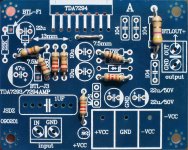
Upper left, the bootstrap is 47u. Standby has a 10u cap, mute does not. The input load is 12k. The gain divider is 27k vs 510R+220R. Resistors shown more clearly at post 414. The NFB-Shunt Cap is 660u with an additional bypass cap under the board (try a 1u or smaller electrolytic as your first guess). Plastic power terminal modified to support the MBR schottky for to block blur and block crosstalk. Picofareds RF filter cap added to small signal input area under board. More elegant small input circuit not yet built. The amp is playing nicely direct driven from my computer.
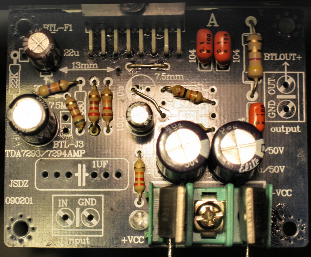
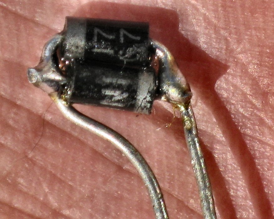
Here is the safety clipper that plugs in right next to the NFB-Shunt Cap. The connection is clipper parallel to large nfb-shunt cap. It doesn't clip audio. This little clipper prevents charge build up in your cap so that it doesn't knock out the inputs like a taser. The unit shown limits the charge to 0.65v with 1n4007 didoes. If your rails are quite lopsided, two such units can be put series for 1.3v limit. This unit shown in the photo below, prevents the destruction of the chip's input.
It came on playing efficiently while the bulb tester remains dark.
Upper left, the bootstrap is 47u. Standby has a 10u cap, mute does not. The input load is 12k. The gain divider is 27k vs 510R+220R. Resistors shown more clearly at post 414. The NFB-Shunt Cap is 660u with an additional bypass cap under the board (try a 1u or smaller electrolytic as your first guess). Plastic power terminal modified to support the MBR schottky for to block blur and block crosstalk. Picofareds RF filter cap added to small signal input area under board. More elegant small input circuit not yet built. The amp is playing nicely direct driven from my computer.
Here is the safety clipper that plugs in right next to the NFB-Shunt Cap. The connection is clipper parallel to large nfb-shunt cap. It doesn't clip audio. This little clipper prevents charge build up in your cap so that it doesn't knock out the inputs like a taser. The unit shown limits the charge to 0.65v with 1n4007 didoes. If your rails are quite lopsided, two such units can be put series for 1.3v limit. This unit shown in the photo below, prevents the destruction of the chip's input.
Attachments


Last edited:
- Status
- This old topic is closed. If you want to reopen this topic, contact a moderator using the "Report Post" button.
- Home
- Amplifiers
- Chip Amps
- Optimizing TDA7294 Output