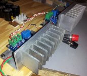
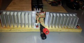
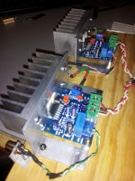
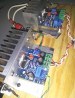
Made some progress on the TDA kit project. Added more metal to the heat management system and tidied up the power and signal wires. The build sounds great on the big speakers (shown here with mini 2496 DAC driving Sunflowers)
The new power supply made bigger improvements than I had anticipated. My biggest gripe with the stock build was a low ceiling before the sound got mushy on the top end, as well as what I interpret as IM distortion. For the most part, that lack of headroom is gone. The natural clarity and warmth of the chip can be heard well above 90% of the volume slider as opposed to trouble near 65 - 70% with the old power supply. The amp is still limited in sparkle and shimmer compared to some of my LM3886 builds, but the dynamics are full and immediate. The low end sounds more stable and accurate but no sensation of extension is perceived. There is nothing missing but I'm used to a heavier bottom output from the MyRefs/FEs.
I'm adding a link to a "torture test" track I use for complexity and wide response. It has top end cymbal/cymbal bell, pure tone sounds in all ranges, active - sometimes heavy bass activity and wide dynamic changes. Everything you hear in the middle is super with the new PS. If my wishes were granted there would be a bit more grunt on the kick drum and bass, Dario's FEs really shake the floor with engulfing resonance on those low runs. Better definition of the segment containing the shaker along with some improvement in depth of stage might well be a mater of component choice. I don't know how much PCB design effects those two elements. The piano runs on the track are clean, musical, warm and accurate. I think that's the audio segment this chip can handle best - almost perfect to my ears.
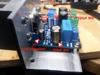
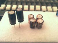
So the next step is Daniel's bottleneck. I'm wondering if I can use one of the 220 uF caps I have instead of two 100s. The pic shows what I found in the stash.
I put some resistors in my Mouser cart as part of the power supply upgrade and snubbers but am wondering if that provides anything more that a voltage match. After the break-in I'm reading +32.2 VDC and -32.19 (sometimes flashing to -32.2) There is no problem adding the snubbers if it is still recommended.
Great work on the power supply Daniel - a very significant improvement.
Torture Track download
The new power supply made bigger improvements than I had anticipated. My biggest gripe with the stock build was a low ceiling before the sound got mushy on the top end, as well as what I interpret as IM distortion. For the most part, that lack of headroom is gone. The natural clarity and warmth of the chip can be heard well above 90% of the volume slider as opposed to trouble near 65 - 70% with the old power supply. The amp is still limited in sparkle and shimmer compared to some of my LM3886 builds, but the dynamics are full and immediate. The low end sounds more stable and accurate but no sensation of extension is perceived. There is nothing missing but I'm used to a heavier bottom output from the MyRefs/FEs.
I'm adding a link to a "torture test" track I use for complexity and wide response. It has top end cymbal/cymbal bell, pure tone sounds in all ranges, active - sometimes heavy bass activity and wide dynamic changes. Everything you hear in the middle is super with the new PS. If my wishes were granted there would be a bit more grunt on the kick drum and bass, Dario's FEs really shake the floor with engulfing resonance on those low runs. Better definition of the segment containing the shaker along with some improvement in depth of stage might well be a mater of component choice. I don't know how much PCB design effects those two elements. The piano runs on the track are clean, musical, warm and accurate. I think that's the audio segment this chip can handle best - almost perfect to my ears.
So the next step is Daniel's bottleneck. I'm wondering if I can use one of the 220 uF caps I have instead of two 100s. The pic shows what I found in the stash.
I put some resistors in my Mouser cart as part of the power supply upgrade and snubbers but am wondering if that provides anything more that a voltage match. After the break-in I'm reading +32.2 VDC and -32.19 (sometimes flashing to -32.2) There is no problem adding the snubbers if it is still recommended.
Great work on the power supply Daniel - a very significant improvement.
Torture Track download
Attachments
We're not quite done with the power circuit. Louder mids at the amplifier board power circuit sounds exactly like poor treble combined with poor bass.The amp is still limited in sparkle and shimmer compared to some of my LM3886 builds, but the dynamics are full and immediate. The low end sounds more stable and accurate but no sensation of extension is perceived. There is nothing missing but I'm used to a heavier bottom output from the MyRefs/FEs.
With your report of both insufficient bass and treble, I recommend increasing the 22u amplifier board power caps up to 220u caps before proceeding with other small signal fine tuning. On your board, this is the pair of caps located at the DC screw terminals of the amplifier board. The only reason I can think of for the kit to have come with such a bizarre value is that the smaller caps aren't as easily flattened in the mail.
For example 100u would be slightly too small (albeit quite clear at the cost of the mids being somewhat louder than both treble and bass), so I've no idea why that kit board has 22u, which is not really valid.
For TDA7294, amp board power caps of 470u would be too large and maybe dull, so at that point you'd need to step back, try the rail to rail cap and possibly try multiple parallel 100u caps or parallel 220u caps. But, I think that simply swapping the 22u for 220u and then using a rail to rail cap, could be a home run.
For example, if you want to use small power caps on the amp board (not smaller than 100u), then a great trick to turn down the mids while increasing resolution is one ~2u polyester cap from V+ to V- (rail to rail) at the DC power terminals of the amplifier board.
EDIT: On your caps photo, I see some 50v compact 220u caps that could be ideal for amplifier board power caps (to replace that pair of 22u located at the amp board DC terminals). We must undo the shout at the power circuit before removing the extra warm bottleneck at small signal.
After turning down the midrange loudness at the power circuit so that we have a chance at hearing the bass and treble, then we can try a couple of other things.
Fix the bootstrap cap bass blocker (install 47u).
Fix the NFB-shunt cap bass blocker (see post#27).
Fix the treble:
You can head over to the Radio Shack for some of the 10n (0.01u) and 22n (0.022u) little green polyester caps and try them in parallel with Input cap and NFB-shunt cap to get that treble sparkle.
Snubbing the transformer's secondaries is for audio quality and that is recommended. This is closing the barn door Before the horse gets out. It can probably help the DAC too, because it is highly effective on both unregulated and regulated power supplies.There is no problem adding the snubbers if it is still recommended.
Last edited:
Hey Daniel - et al.,
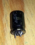
I'm up against a conflict I thought might develop. I'm not the best Mouser searcher, but the smallest 220uF 50V cap I see is 10mm in diameter - as are those in my posted photo. Mounting those near the DC terminals is possible but somewhat kludgey. Those alone are acceptable but I'm anticipating additional component swaps might result in quite a conglomeration.
My original thought about upgrading the existing kit/board had the intention of staying close to the format/footprint as shipped from the vendors. I have no doubt that Daniel's suggestions will produce the improvements, as evidenced by the great PS results, but I fear trying to pack too much in a small area might be a questionable path. This is based on the assumption that a new larger board is still in the offing and might better accommodate a wider selection of components.
With all the other amp builds around my castle , considering this kit as a bench/experimental project is certainly valid and will provide needed learning opportunities for me. I am however somewhat concerned that we are singing a duet and other potential builders may not desire to join in at this point.
So let me pose a couple questions.
Are there some DIYers watching the thread with the intention of buying/upgrading the existing kit. If so please let us know.
Haven't heard from KSTR and others about any new PCB developments in a while. So is there any new information/progress available on that front?
Is there interest in moving toward a P2P project for experimenting while the new design is being developed. That is an approach that I intend to do at some point just because it sounds like fun.
So please consider this post an opportunity to calibrate our direction and collect any thoughts that might be floating around. What say ye all?
P.S. I still firmly believe the TDA7294 is a real gem. It reminds me of what I used to say about my daughter-in-law when I was mad at her: "A little Sherman tank on roller skates"
I'm up against a conflict I thought might develop. I'm not the best Mouser searcher, but the smallest 220uF 50V cap I see is 10mm in diameter - as are those in my posted photo. Mounting those near the DC terminals is possible but somewhat kludgey. Those alone are acceptable but I'm anticipating additional component swaps might result in quite a conglomeration.
My original thought about upgrading the existing kit/board had the intention of staying close to the format/footprint as shipped from the vendors. I have no doubt that Daniel's suggestions will produce the improvements, as evidenced by the great PS results, but I fear trying to pack too much in a small area might be a questionable path. This is based on the assumption that a new larger board is still in the offing and might better accommodate a wider selection of components.
With all the other amp builds around my castle
, considering this kit as a bench/experimental project is certainly valid and will provide needed learning opportunities for me. I am however somewhat concerned that we are singing a duet and other potential builders may not desire to join in at this point.So let me pose a couple questions.
Are there some DIYers watching the thread with the intention of buying/upgrading the existing kit. If so please let us know.
Haven't heard from KSTR and others about any new PCB developments in a while. So is there any new information/progress available on that front?
Is there interest in moving toward a P2P project for experimenting while the new design is being developed. That is an approach that I intend to do at some point just because it sounds like fun.
So please consider this post an opportunity to calibrate our direction and collect any thoughts that might be floating around. What say ye all?
P.S. I still firmly believe the TDA7294 is a real gem. It reminds me of what I used to say about my daughter-in-law when I was mad at her: "A little Sherman tank on roller skates"
Bob, I have been following this thread and the p2p thread closely (though the p2p thread seems to have gotten a little off track). I am wraping up a couple of other projects right now, but when they are singing it wont be long until I will have to start another (DIY is compairable to chain smoking, hopefully better for you though ).
I would be interested at some point in an optimized board, but like you the p2p project sounds like fun, and I think that is what I will go forward with. This week I recieved a mouser order that among other things included a pair of TDA7294 chips and a few of the items for the amplifier circuit. I also have a few of the caps etc. on hand allready so I will order the rest when I go through my inventory and see what I do and dont have. Aside from assorted wire, I have none of the elements of the power supply and I am still going back and forth on what value cap I will use. A dual mono power supply will be costly with above average components, but I think definately worth it. With that in mind it may be a few weeks before I am ready to really get started, but this project in some form will be the next.
hopefully I will have more to contribute, but in the meantime I will be following along.
).I would be interested at some point in an optimized board, but like you the p2p project sounds like fun, and I think that is what I will go forward with. This week I recieved a mouser order that among other things included a pair of TDA7294 chips and a few of the items for the amplifier circuit. I also have a few of the caps etc. on hand allready so I will order the rest when I go through my inventory and see what I do and dont have. Aside from assorted wire, I have none of the elements of the power supply and I am still going back and forth on what value cap I will use. A dual mono power supply will be costly with above average components, but I think definately worth it. With that in mind it may be a few weeks before I am ready to really get started, but this project in some form will be the next.
hopefully I will have more to contribute, but in the meantime I will be following along.
Thanks Will,
Looking forward to hearing how you progress. I lucked out on the PS as I already had half the 3300 uF caps and more LEDs than needed. If/when the new PCB shows I think it will be well worth investing in discrete power supplies if in fact that is recommended. I'm hooked and am anticipating the next level of sophistication beyond what I built.
Thanks for keeping in touch.
No Green Smoke
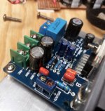
As luck would have it the only 220/50 caps on hand were used, with little stubs for leads. But the handy-dandy Dremell tool (cut off some green plastic), pointy needle nose pliers and a tiny drill got everything to fit.
The board with the new caps runs ~ 3-4 degrees warmer topping out at 84 on the chip flange. HS is ~ 91 with the bulb tester.
I'll let it marinate for a time tonight on the tester and the bench speakers while I create some good mono tracks for comparative tests in the morning.
Upwards and onward.
Attachments
You did very nicely with the build quality too!!. . . The new power supply made bigger improvements than I had anticipated. My biggest gripe with the stock build was a low ceiling before the sound got mushy on the top end, as well as what I interpret as IM distortion.
For the most part, that lack of headroom is gone.
The natural clarity and warmth of the chip can be heard well above 90% of the volume slider as opposed to trouble near 65 - 70% with the old power supply. . . .
Great work on the power supply Daniel - a very significant improvement.
With the 200va transformer, I estimate that it is probably safe to hook up those 4 ohm speakers.
Well, sir, the kit is tuned to create enough 2nd order harmonic distortion, warm midbass bloom to be loud enough to level out with the loud mids problem of the 22u power caps. This comes at the cost of bass extension. So, to unscrew that problem, grab the 220u caps, take aim, and push!bcmbob said:I'm up against a conflict I thought might develop. I'm not the best Mouser searcher, but the smallest 220uF 50V cap I see is 10mm in diameter - as are those in my posted photo. Mounting those near the DC terminals is possible but somewhat kludgey. Those alone are acceptable but I'm anticipating additional component swaps might result in quite a conglomeration.
After you get that done, we can lower the pitch of the feedback-shunt RC to enable higher resolution bass.With any change to larger caps, the temps will go slightly warmer until the rail-to-rail cap is installed, which, if the right size/cap is found, will decrease midrange loudness (more room to tune up for bigger bass), clarify midrange, and decrease temps.
Last edited:
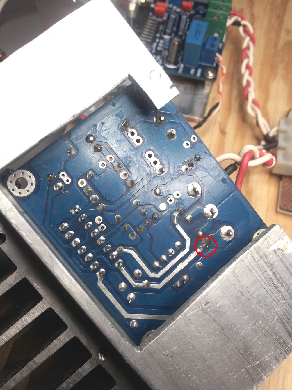
Need to finish soldering the pin7 jumper?
If the predrive goes missing the V+, it might become annoyed or have a fit.
While you're at it, you can relocate the feedback resistor off the board, and then, onto the chip from pin2 to pin14 (trackside, under board, right at the chip).
If the predrive goes missing the V+, it might become annoyed or have a fit.
While you're at it, you can relocate the feedback resistor off the board, and then, onto the chip from pin2 to pin14 (trackside, under board, right at the chip).
Last edited:
The NFB-shunt cap size has improved and will allow more bass to pass intact, however fully utilizing that also takes the right size feedback-shunt resistor. Although the 50v caps might (or might not) be better, you can actually use 25v caps at small signal if you need something physically smaller. This is "inverting input cap" and takes the same amount of care and experimentation as any input cap. And, it is big.
Therefore. . .
Treble quality:
You'll really want to experiment with some little treble bypass caps in parallel with your NFB-shunt cap.
Although any single large value cap can have its treble patched up to excellence by much experimentation for finding a just right bypass cap for it. . . you might prefer the speed and ease of identical models of parallel 100u caps to get a 200u value without the bother of lengthy experimentation.
Last edited:
I have a bunch of small caps from the MyRef FE tuning process and already started sorting them out. A lot of 22 - 47 nF Wima and CDE Mica.
I tried to fit some 100/50 (new but with short leads), but it would have taken too much fiddling. I'll order two more of the 35V with long leads to match what I have and shoot for 200 on the nose.
I tried to fit some 100/50 (new but with short leads), but it would have taken too much fiddling. I'll order two more of the 35V with long leads to match what I have and shoot for 200 on the nose.
Attachments
For the NFB-shunt cap selection workout, you can install a pair of vertical pins made of bell wire pieces. The pins would need something like a "Z" shaped kink with a solder ball applied to the "Z" at the topside of the board, both for wider spacing and as a blockade so that we can't accidentally push the tracks loose (the "Z" and their little solder blobs supports the pins--the tracks don't). The prospect is very much like prefab pins, except that homebrew can give wider spacing. The pins added topside can allow stacking the caps sideways atop the board, and the main feature of that is plenty of room to work without so much labor between swaps.
Preferred signal caps are the usual contenders, with Nichicon FW, Panasonic FC, Sanyo, Ruby, "non-pet" Elite and Elna Cerafine. The most likely of those to do 100||100u or 220u||220u most easily is Nichicon FW because of its extended high range, but the Panasonic FC may deliver higher resolution and there is no way to tell in advance which might be better. The Elna Cerafine may be most charming, but any size larger than 1u always requires a treble bypass cap (so popular that the specific name for Cerafine||polyester is "the classic combo"). Easiest possible general purpose treble bypass cap, if there is such a thing, is Nichicon ES 0.47uF (and smaller sizes of Nichicon polar or bi-polar electrolytic caps). Second easiest is 22u and 10u little polyester dip caps--the little green things you can find at the Radio Shack and probably also *somewhere* on Mouser.
Directly affecting such a large selection labor is:
#1). Amp board power circuit caps versus midrange loudness (for level response).
#2). Rail to rail cap versus midrange resolution (decreased upper-midrange distortion, and cooler running).
#3). Feedback-Shunt resistor and cap versus bass resolution (see post#27)
#4). Input cap value (should begin with a known good 1uF).
#5). Feedback resistor current (too little is noisy for poor resolution, too much is audio masher for poor resolution, so the middle ground must be found).
Rather fascinating that feedback-shunt resistor and cap are chosen by voltage and bass; however, feedback resistor is chosen by current and imaging size of a single/each speaker (audible resolution micro-detail).
Needless to say, it would be good to install plausible values for amp board power caps and rail to rail cap before going on a small signal workout.
Last edited:
Had a Murphy's Day yesterday, sorry.
At first I couldn't hear a lot of difference with the cap transplants. With mono sources I separated my bench speakers to 20" and stuck my head in between them.. I perceived a definite increase of highs and dynamics with the new caps in that position but could not hear as much when I backed off to about 4 feet.
Again, with the big speakers there was nothing that jumped out at first. Then I realized no matter the distance from the speakers it sounded like I had wax in my left ear. The modded amp is definitely brighter, clearer and more responsive - I'll guess ~ 10 - 20% or so. I think that's the "clearing the bottleneck" Daniel has been talking about. I plan to keep the other amp stock through a few more upgrades.
BTW, I used a great little program named REAPER to convert a couple tracks to mono. It's from the same folks that did Winamp and is worth a look/trial. It produced flac files that are playable on a Galaxy S II. Not a lot of volume but high quality.
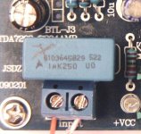
Daniel, If you would please paint in the Z extensions you suggest. I looked back at the photo you posted when you received your board but couldn't decipher.
Also, I'm still using the stock input cap (i believe) and noticed you have an alternative. Any info?
At first I couldn't hear a lot of difference with the cap transplants. With mono sources I separated my bench speakers to 20" and stuck my head in between them.
. I perceived a definite increase of highs and dynamics with the new caps in that position but could not hear as much when I backed off to about 4 feet.Again, with the big speakers there was nothing that jumped out at first. Then I realized no matter the distance from the speakers it sounded like I had wax in my left ear. The modded amp is definitely brighter, clearer and more responsive - I'll guess ~ 10 - 20% or so. I think that's the "clearing the bottleneck" Daniel has been talking about. I plan to keep the other amp stock through a few more upgrades.
BTW, I used a great little program named REAPER to convert a couple tracks to mono. It's from the same folks that did Winamp and is worth a look/trial. It produced flac files that are playable on a Galaxy S II. Not a lot of volume but high quality.
Daniel, If you would please paint in the Z extensions you suggest. I looked back at the photo you posted when you received your board but couldn't decipher.
Also, I'm still using the stock input cap (i believe) and noticed you have an alternative. Any info?
Attachments
Yes, non-audiometric values are like ears full of wax. That weird pressure is foldback distortion of the bass from allowing more bass into the amp than it could pass through. If you didn't change the resistor values, then there is actually a lot of bottleneck still present. See again, post#27
True that TDA7294 can't do high end sound unless bass is allowed to pass through the feedback-shunt RC intact. Ways to resolve this particular bottleneck is:
Decrease input cap size (1u or smaller).
Increase NFB-Shunt cap size (greater than 199u).
Increase Feedback-Shunt resistor value (greater than 1.1k).
I'm after both increases.
Note1
Finishing power circuit tuning first, to make the job easier
Before proceeding, I'd again like to remind that using the rail to rail cap could make the small signal fine tuning a lot easier and the amp slightly cooler and cleaner so that it has more capacity for powerful clear output. We could proceed without that part, but I wouldn't know why it would be omitted.
Note2
The large size caps we're using for NFB-shunt cap probably necessitate a tiny companion--the treble bypass cap, which can prevent either mumbling or shout effect of treble roll-off. If there's any of that unpleasantness, do be sure to fix it with a cute little bypass cap in parallel to the larger cap. Even a rough approximation can be more pleasant than listening to an error near ear sensitivity peak.
Example with parallel pair of 220u
To do 220u||220u (440u) NFB-shunt cap, we'd need a feedback-shunt resistor of 1.5k. In that case, plausible feedback resistor values are then in a range from 39k to 56k.
Gain versus Dynamics
Given the resource of clean power, I'd certainly make a try for more fun dynamics by setting high gain. The 56k feedback resistor with 1.5k feedback-shunt resistor is in the ballpark for having your cake and eating it too. I would suggest to ballpark at this point, and then experiment from there.
You can try reducing the gain (47k feedback instead of 56k) to see if the soundfield may or may not get bigger, and determine and keep the option that you like best.
However. . .
I predict that with either the Galaxy S II or a normal computer, that you would most like the high gain option (38X) because a source that isn't straining is a good upgrade, since a source in good condition is more attractive to amplify. Assisting source quality with a high gain power amp is generally far more beneficial than the rather small negative consequences of high gain at the amp. A different way to do it is install a preamp, but I cannot determine if the loss of high gain amp or if the insertion loss of preamp is the correct compromise. Perhaps it is personal taste. Either option requires clean power.
Resistor swapping Labor
Finding the ballpark and then fine tuning from there, will take a lot of parts swapping. You can easily paste and remove resistors from trackside (without wearing out a desoldering iron), but caps are not so easy. Adding pins doesn't work for the resistors, but it can make for ease in cap swapping. . .
Cap Swapping Labor (add Pins to make it easy)
Before doing the pins and cap interviews, plausible resistor values would be good, and then. . .
Leftmost photo (in your post above), the spots marked 1uF and 47uF are both signal caps, there's gain on them and it will take some experimentation, such as "contest of 5 peers" interviews to find ideal capacitors for both locations. The "z extensions" are nothing other than homebrew pins that stick out the top and give you room to test drive at least 5 capacitor candidates (plus find them attractive bypass cap partners) quickly and without wearing out the PCB traces or desoldering iron. A touch of normal soldering iron will free capacitors from pins so much more quickly and in that way you can conduct interviews more easily. The pins can be removed and the "winning" caps can be installed normally after the "interviews" are finished. May I suggest current production high availability parts?
Cap quality control
In a 5 peers contest, you've already got the 1u polyester you've been using for input cap and your NFB-shunt cap is a 220u panasonic. That's good. To finish the contest, you'd find 4 more contenders for each location in comparison test. There's gain on these two caps, so that high end results necessitates a quality control. Contenders that do poorly at first, may do excellence if given a just right bypass cap as helper, so yes, there is a bit of labor involved.
Validity check
The shield function of the amplifier board power caps requires that the NFB-shunt cap isn't larger than the combined value of the amplifier board power caps (and preferably nfb-shunt cap isn't larger than 1 of the amplifier board power caps). At near maximum scale, a pair of 270uF for amplifier board power caps (one per rail) and a parallel pair of 270uF for a low loss 540uF NFB-shunt cap, gives us an answer that the feedback-shunt resistor can't be smaller value than 1.2K. We need 1.2k or larger values, and range of validity is 1.2k through 3.3k. If we're not inside that range, then we're not in the ballpark.
Guitar amp & Bi-amp
The 680R doesn't work unless we wanted a bottlenecked mid-fi or to decrease the input cap value as may be used in the mids&treble portion of a bi-amp system or guitar amp. Otherwise, the 680R is probably dreadful.
Band-aid fix
A DC Tracker may (or may not) provide a dodge that could let us use a 680R feedback-shunt resistor, but I would suggest to change the resistor value to something plausible instead of adding a complex and noisy circuit with caps of its own.
That weird pressure is foldback distortion of the bass from allowing more bass into the amp than it could pass through. If you didn't change the resistor values, then there is actually a lot of bottleneck still present. See again, post#27True that TDA7294 can't do high end sound unless bass is allowed to pass through the feedback-shunt RC intact. Ways to resolve this particular bottleneck is:
Decrease input cap size (1u or smaller).
Increase NFB-Shunt cap size (greater than 199u).
Increase Feedback-Shunt resistor value (greater than 1.1k).
I'm after both increases.
Note1
Finishing power circuit tuning first, to make the job easier
Before proceeding, I'd again like to remind that using the rail to rail cap could make the small signal fine tuning a lot easier and the amp slightly cooler and cleaner so that it has more capacity for powerful clear output. We could proceed without that part, but I wouldn't know why it would be omitted.
Note2
The large size caps we're using for NFB-shunt cap probably necessitate a tiny companion--the treble bypass cap, which can prevent either mumbling or shout effect of treble roll-off. If there's any of that unpleasantness, do be sure to fix it with a cute little bypass cap in parallel to the larger cap. Even a rough approximation can be more pleasant than listening to an error near ear sensitivity peak.
Example with parallel pair of 220u
To do 220u||220u (440u) NFB-shunt cap, we'd need a feedback-shunt resistor of 1.5k. In that case, plausible feedback resistor values are then in a range from 39k to 56k.
Gain versus Dynamics
Given the resource of clean power, I'd certainly make a try for more fun dynamics by setting high gain. The 56k feedback resistor with 1.5k feedback-shunt resistor is in the ballpark for having your cake and eating it too. I would suggest to ballpark at this point, and then experiment from there.
You can try reducing the gain (47k feedback instead of 56k) to see if the soundfield may or may not get bigger, and determine and keep the option that you like best.
However. . .
I predict that with either the Galaxy S II or a normal computer, that you would most like the high gain option (38X) because a source that isn't straining is a good upgrade, since a source in good condition is more attractive to amplify. Assisting source quality with a high gain power amp is generally far more beneficial than the rather small negative consequences of high gain at the amp. A different way to do it is install a preamp, but I cannot determine if the loss of high gain amp or if the insertion loss of preamp is the correct compromise. Perhaps it is personal taste. Either option requires clean power.
Resistor swapping Labor
Finding the ballpark and then fine tuning from there, will take a lot of parts swapping. You can easily paste and remove resistors from trackside (without wearing out a desoldering iron), but caps are not so easy. Adding pins doesn't work for the resistors, but it can make for ease in cap swapping. . .
Cap Swapping Labor (add Pins to make it easy)
Before doing the pins and cap interviews, plausible resistor values would be good, and then. . .
Leftmost photo (in your post above), the spots marked 1uF and 47uF are both signal caps, there's gain on them and it will take some experimentation, such as "contest of 5 peers" interviews to find ideal capacitors for both locations. The "z extensions" are nothing other than homebrew pins that stick out the top and give you room to test drive at least 5 capacitor candidates (plus find them attractive bypass cap partners) quickly and without wearing out the PCB traces or desoldering iron. A touch of normal soldering iron will free capacitors from pins so much more quickly and in that way you can conduct interviews more easily. The pins can be removed and the "winning" caps can be installed normally after the "interviews" are finished. May I suggest current production high availability parts?
Cap quality control
In a 5 peers contest, you've already got the 1u polyester you've been using for input cap and your NFB-shunt cap is a 220u panasonic. That's good. To finish the contest, you'd find 4 more contenders for each location in comparison test. There's gain on these two caps, so that high end results necessitates a quality control. Contenders that do poorly at first, may do excellence if given a just right bypass cap as helper, so yes, there is a bit of labor involved.
Validity check
The shield function of the amplifier board power caps requires that the NFB-shunt cap isn't larger than the combined value of the amplifier board power caps (and preferably nfb-shunt cap isn't larger than 1 of the amplifier board power caps). At near maximum scale, a pair of 270uF for amplifier board power caps (one per rail) and a parallel pair of 270uF for a low loss 540uF NFB-shunt cap, gives us an answer that the feedback-shunt resistor can't be smaller value than 1.2K. We need 1.2k or larger values, and range of validity is 1.2k through 3.3k. If we're not inside that range, then we're not in the ballpark.
Guitar amp & Bi-amp
The 680R doesn't work unless we wanted a bottlenecked mid-fi or to decrease the input cap value as may be used in the mids&treble portion of a bi-amp system or guitar amp. Otherwise, the 680R is probably dreadful.
Band-aid fix
A DC Tracker may (or may not) provide a dodge that could let us use a 680R feedback-shunt resistor, but I would suggest to change the resistor value to something plausible instead of adding a complex and noisy circuit with caps of its own.
Last edited:
Well, there's two resistors that need attached firmly and with excellent quality fluxed solder connections:
Feedback resistor
Input load resistor
If either of those should happen to come loose, the amplifier may do something unexpected and a bit disturbing.
So, for this phase of experimentation with the hasty component swapping, I suggest to use speaker protection (monobloc version shown):
![329812d1360601879-beginners-gainclone-hifi-lm1875-amplifier-board-bipolar.gif]bi-polar 6600u](https://www.diyaudio.com/forums/attachments/chip-amps/329812d1360601879-beginners-gainclone-hifi-lm1875-amplifier-board-bipolar.gif]bi-polar 6600u)
High quality version shown in the photo and still costs less than speakers.
Either positive to positive or negative to negative orientation works.
If used with split rail amp, one could add optional 100K drainers.
You can put this in series to either speaker- OR speaker+.
Small size, low cost, 35v compact caps are used.
Location is at speaker jack or speaker.
Drive first some cable.
Feedback resistor
Input load resistor
If either of those should happen to come loose, the amplifier may do something unexpected and a bit disturbing.
So, for this phase of experimentation with the hasty component swapping, I suggest to use speaker protection (monobloc version shown):
High quality version shown in the photo and still costs less than speakers.
Either positive to positive or negative to negative orientation works.
If used with split rail amp, one could add optional 100K drainers.
You can put this in series to either speaker- OR speaker+.
Small size, low cost, 35v compact caps are used.
Location is at speaker jack or speaker.
Drive first some cable.
Last edited:
My components are fairly simple.
For the amplifier board component swapping, optimization, selection play. . .
Personally, all of the caps that I'd use for signal, do all happen to have long leads.
Little green 4.7n, 10n, 22n polyester dip caps have long leads
Audio electrolytic caps have long leads.
472 470p ceramic from the radio shack has long leads, and a ceramic cap of such a small value isn't for passing audio but rather removing some inductance sound issues from big bodied nfb-shunt caps.
Whoops! Okay, I was mistaken. AVX little yellow radio grade polyester box caps marked with a T * in very, very small values can be used for a big blast of airy treble. They're probably overkill, but they are usable. And, those do have short leads.
Audiophile tomfoolery that happens to cost less. . .
Diy audiophile resistors:
There's, no need to buy high end resistors for feedback divider when you can make ordinary parts do the same tasks. The feedback divider controls open loop gain and therefore hearing difference is possible due to the vast gain that is applied to those resistors (only those). When I finally thought of it for long enough, there was plausible science in some (but not all) audiophile resistor selections.
On research, this is plausible:
Lower noise with higher current tolerances, low inductance feedback resistor, moving the feedback resistor onto the chip pins, slightly lower gain at RF and ultra low capacitance feedback-shunt resistor. With that information revealed, it is then doable with ordinary parts at low cost . . .
The carbon film resistors at Radio Shack are Xicon with the nice thick leads. Mouser also has Xicon and Koa carbon film.
1). Feedback resistor:
A paralleled pair of identical value 1/4 watt Xicon or Koa carbon film, with minimal pin length between the two identical resistors, (spiral twist the pins, flux, and solder so there's no gap between the resistors) makes a high end carbon resistor with low inductance leads for feedback resistor. This small and sturdy assembly can go trackside, right on the chip pins. For example 100k||100k makes 50k feedback resistor. The extremely low inductance is a good thing. Carbon comp, carbon film, metal comp or metal film can be used since the paralleling has enforced a quality control already. For feedback resistor, I think we'd like to assure zero loss at RF.
2). Feedback-Shunt resistor:
However, for feedback-shunt resistor, a solo 1/2w Xicon carbon film could be quite attractive. I wish I had ordered 1.33k, 1.5k, 1.68k 1.8k, 2.0k 1/2w carbon film from Mouser, for testing each. Although we want the HF loss and low capacitance typical of a single 1/2w carbon film resistor, we don't want that to happen inside the audio band, so the resistor must be of decent quality carbon or carbon film (Xicon or Koa), so that the miniscule loss happens way up at RF, effectively decreasing the gain on noise. It doesn't do much, but even a tiny step in the right direction is nice when so easily done. At feedback shunt, we need the lowest capacitance resistor, and a good brand of 1/2w carbon film works nicely. Other ultra low capacitance resistors typical for stopper use in tube amplifiers may work well--For feedback-Shunt resistor, I think we'd like to use stopper suitable resistors and avoid metal film.
Current vs resistor wattage:
At least we could say that the resulting sturdy feedback divider could handle double the current without degrading the signal. More audio, less noise = more amp power. So, if you're planning on some full blast fun, this sturdy, inexpensive, audiophile resistor prospect might make a tiny, yet appreciable, difference.
Diy audiophile resistors:
There's, no need to buy high end resistors for feedback divider when you can make ordinary parts do the same tasks.
The feedback divider controls open loop gain and therefore hearing difference is possible due to the vast gain that is applied to those resistors (only those). When I finally thought of it for long enough, there was plausible science in some (but not all) audiophile resistor selections. On research, this is plausible:
Lower noise with higher current tolerances, low inductance feedback resistor, moving the feedback resistor onto the chip pins, slightly lower gain at RF and ultra low capacitance feedback-shunt resistor. With that information revealed, it is then doable with ordinary parts at low cost . . .
The carbon film resistors at Radio Shack are Xicon with the nice thick leads. Mouser also has Xicon and Koa carbon film.
1). Feedback resistor:
A paralleled pair of identical value 1/4 watt Xicon or Koa carbon film, with minimal pin length between the two identical resistors, (spiral twist the pins, flux, and solder so there's no gap between the resistors) makes a high end carbon resistor with low inductance leads for feedback resistor. This small and sturdy assembly can go trackside, right on the chip pins. For example 100k||100k makes 50k feedback resistor. The extremely low inductance is a good thing. Carbon comp, carbon film, metal comp or metal film can be used since the paralleling has enforced a quality control already. For feedback resistor, I think we'd like to assure zero loss at RF.
2). Feedback-Shunt resistor:
However, for feedback-shunt resistor, a solo 1/2w Xicon carbon film could be quite attractive. I wish I had ordered 1.33k, 1.5k, 1.68k 1.8k, 2.0k 1/2w carbon film from Mouser, for testing each. Although we want the HF loss and low capacitance typical of a single 1/2w carbon film resistor, we don't want that to happen inside the audio band, so the resistor must be of decent quality carbon or carbon film (Xicon or Koa), so that the miniscule loss happens way up at RF, effectively decreasing the gain on noise. It doesn't do much, but even a tiny step in the right direction is nice when so easily done. At feedback shunt, we need the lowest capacitance resistor, and a good brand of 1/2w carbon film works nicely. Other ultra low capacitance resistors typical for stopper use in tube amplifiers may work well--For feedback-Shunt resistor, I think we'd like to use stopper suitable resistors and avoid metal film.
Current vs resistor wattage:
At least we could say that the resulting sturdy feedback divider could handle double the current without degrading the signal. More audio, less noise = more amp power. So, if you're planning on some full blast fun, this sturdy, inexpensive, audiophile resistor prospect might make a tiny, yet appreciable, difference.
Last edited:
- Status
- This old topic is closed. If you want to reopen this topic, contact a moderator using the "Report Post" button.
- Home
- Amplifiers
- Chip Amps
- Optimizing TDA7294 Output